1 Cover
2 Series Page IEEE Press 445 Hoes Lane Piscataway, NJ 08854 IEEE Press Editorial Board Ekram Hossain, Editor in Chief Jón Atli Benediktsson Xiaoou Li Jeffrey Reed Anjan Bose Lian Yong Diomidis Spinellis David Alan Grier Andreas Molisch Sarah Spurgeon Elya B. Joffe Saeid Nahavandi Ahmet Murat Tekalp
3 Title Page Electromagnetic Vortices: Wave Phenomena and Engineering Applications Edited by Zhi Hao Jiang Southeast University Douglas H. Werner The Pennsylvania State University
4 Copyright Page
5 Dedication
6 About the Editors
7 List of Contributors
8 Preface
9 Part I: Fundamentals and Basics of Electromagnetic Vortices 1 Fundamentals of Orbital Angular Momentum Beams 1.1 Electromagnetic Fields Carry Orbital Angular Momentum 1.2 OAM Beams; Properties and Analogies with Conventional Beams 1.3 Communicating Using OAM: Potentials and Challenges 1.4 OAM Generation Methods 1.5 Summary and Perspectives Appendix 1.A OAM Far-field Calculation References 2 OAM Radio – Physical Foundations and Applications of Electromagnetic Orbital Angular Momentum in Radio Science and Technology 2.1 Introduction 2.2 Physics 2.3 Implementation Appendix A References
10 Part II: Physical Wave Phenomena of Electromagnetic Vortices 3 Generation of Microwave Vortex Beams Using Metasurfaces 3.1 Introduction 3.2 Metasurfaces for Vortex‐beam Generation 3.3 Conclusion Acknowledgments References 4 Application of Transformation Optics and 3D Printing Technology in Vortex Wave Generation 4.1 Introduction 4.2 Theoretical Basis of Transformation Optics and 3D Printing 4.3 Several Applications of Transformation Optics in Vortex Waves 4.4 Conclusions References 5 Millimeter‐Wave Transmit‐Arrays for High‐Capacity and Wideband Generation of Scalar and Vector Vortex Beams 5.1 Introduction 5.2 Vector Vortex Beams and Hybrid‐Order PSs 5.3 Millimeter‐Wave Transmit‐Array Unit Cell Designs 5.4 Millimeter‐Wave Transmit‐Arrays for Vortex Beam Multiplexing 5.5 Conclusion Acknowledgment References 6 Twisting Light with Metamaterials 6.1 Introduction 6.2 OAM Beams on the Nanoscale 6.3 Active OAM Sources 6.4 OAM Light in Engineered Nonlinear Colloidal Systems 6.5 Conclusion References 7 Generation of Optical Vortex Beams 7.1 Introduction 7.2 Basic Theory of Optical Vortex 7.3 Generation of Optical Vortex 7.4 Generation of Novel Vortex Beams 7.5 Conclusion References 8 Orbital Angular Momentum Generation, Detection, and Angular Momentum Conservation with Second Harmonic Generation 8.1 Orbital Angular Momentum Generation and Detection 8.2 AM Conservation: Nonlinear Optics 8.3 Conclusion References
11 Part III: Engineering Applications of Electromagnetic Vortices 9 Orbital Angular Momentum Based Structured Radio Beams and its Applications 1 9.1 Introduction 9.2 PS–OAM Based Structured Beams 9.3 Antennas for Structured Beams 9.4 Potential Applications 9.5 Conclusion References 10 OAM Multiplexing Using Uniform Circular Array and Microwave Circuit for Short‐range Communication 10.1 Introduction 10.2 OAM Multiplexing System and its Mechanism 10.3 OAM Multiplexing for Short‐range Communications 10.4 Conclusion and Key Challenges References 11 OAM Communications in Multipath Environments 11.1 Introduction 11.2 OAM Communication in Line‐of‐sight Environment 11.3 OAM Multiplexing in Multipath Environment 11.4 Conclusion References 12 High‐capacity Free‐space Optical Communications Using Multiplexing of Multiple OAM Beams 12.1 Introduction 12.2 Challenges for an OAM Multiplexing Free‐space Optical Communication System 12.3 Free‐space Optical OAM Links 12.4 Inter‐channel Crosstalk Mitigation Methods in OAM‐multiplexed FSO Communications 12.5 OAM Multiplexing for Unmanned Aerial Vehicle (UAV) Platforms 12.6 OAM Multiplexing in Underwater Environments 12.7 Summary of this Chapter Acknowledgment References
12 Part IV: Multidisciplinary Explorations of Electromagnetic Vortices 13 Theory of Vector Beams for Chirality and Magnetism Detection of Subwavelength Particles 13.1 Characterization of Azimuthally and Radially Polarized Beams 13.2 Circular Dichroism for a Particle of Subwavelength Size 13.3 Photoinduced Force Microscopy at Nanoscale 13.4 Conclusion References 14 Quantum Applications of Structured Photons 14.1 Introduction 14.2 Photonic Degrees of Freedom 14.3 Single Photon Source: SPDC 14.4 Generation and Detection of Structured Photon Quantum States 14.5 Quantum Key Distribution 14.6 Quantum Simulation with Quantum Walks 14.7 Outlook References
13 Index
14  IEEE PRESS SERIES ON ELECTROMAGNETIC WAVE THEORY
15 End User License Agreement
1 Chapter 1 Table 1.1 OAM generation methods and fabricated prototypes. Table 1.2 Chronicle of milestones regarding OAM.
2 Chapter 2 Table 2.1 Characteristics of the linear and angular momenta.Similarities an... Table 2.2 OAM radio from near the M87* BH.Asymmetry parameter q vs . the rota... Table 2.A.1 Various vectorial products of the Riemann–Silberstein bivector G
3 Chapter 10Table 10.1 Optimal array radius.
4 Chapter 11Table 11.1 Transferred power and crosstalk of each OAM channel [9].
1 Chapter 1 Figure 1.1 Analogy between moving object’s and electromagnetic wave’s angula... Figure 1.2 Normalized aperture field intensity distributions versus ρ / w Figure 1.3 Normalized aperture field intensity line cuts of Laguerre–Gaussia... Figure 1.4 Comparison between conventional and OAM beams. A uniformly illumi... Figure 1.5 Far‐field wavefront of (a) Airy disk and (b, c) Laguerre–Gaussian... Figure 1.6 Normalized directivities of the Airy disk pattern with aperture d... Figure 1.7 Changes of amplitude pattern shape from the reactive near‐field t... Figure 1.8 OAM possible communication links: (a) OAM to the conventional ant... Figure 1.9 OAM communication challenges: (a) receiving with a perfectly alig... Figure 1.10 A schematic of multipath effects of an OAM channel caused by spe... Figure 1.11 A satellite‐based, geostationary navigation and guidance system ... Figure 1.12 OAM shift keying (OAM‐SK) modulation. OAM‐SK takes advantage of ... Figure 1.13 OAM division multiplexing (OAM‐DM) modulation. An independent da... Figure 1.14 A schematic illustrating the concept of three‐dimensional multip... Figure 1.15 A schematic representation of different types of optical fibers.... Figure 1.16 Intensity profiles of LP modes and OAM modes. The constituent ei... Figure 1.17 (a) Cross‐section of a 19‐ring multi‐OAM multi‐ring fiber. (b) R... Figure 1.18 Analogy between conventional and OAM generation principle. Figure 1.19 Comparison between the generation method of conventional antenna... Figure 1.A.1 Schematic of the generation of OAM aperture field.
2 Chapter 2 Figure 2.1 Linear antennas. Figure 2.2 Linear momentum radiated into the far zone from a single short di... Figure 2.3 Angular momentum radiated into the far zone from a single short d... Figure 2.4 Angular momentum radiated from two crossed dipoles. Figure 2.5 Top: OAM spectrum from the results of Event Horizon Telescope (EH... Figure 2.A.1 Source and sensor volumes.
3 Chapter 3Figure 3.1 (a) Configuration of the reflective metasurface setup for vortex‐...Figure 3.2 Geometry of the triple–dipole unit cell and layout of the designe...Figure 3.3 PEC–PMC‐based unit cell and the metasurface consisting of rotated...Figure 3.4 Example of the coding metasurface design. (a) Coding unit cell; (...Figure 3.5 (a) Space–frequency‐domain gradient metasurface.(b) configura...Figure 3.6 Examples of multilayer unit cells combined to form a transmission...Figure 3.7 Metasurface with the source integrated in the same layer.Figure 3.8 Prototype of the vortex‐beam emitter using spoof SPP waveguide. (...
Читать дальше
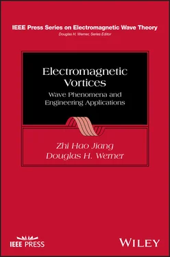
 IEEE PRESS SERIES ON ELECTROMAGNETIC WAVE THEORY
