Artificial Intelligence for Renewable Energy Systems
Здесь есть возможность читать онлайн «Artificial Intelligence for Renewable Energy Systems» — ознакомительный отрывок электронной книги совершенно бесплатно, а после прочтения отрывка купить полную версию. В некоторых случаях можно слушать аудио, скачать через торрент в формате fb2 и присутствует краткое содержание. Жанр: unrecognised, на английском языке. Описание произведения, (предисловие) а так же отзывы посетителей доступны на портале библиотеки ЛибКат.
- Название:Artificial Intelligence for Renewable Energy Systems
- Автор:
- Жанр:
- Год:неизвестен
- ISBN:нет данных
- Рейтинг книги:5 / 5. Голосов: 1
-
Избранное:Добавить в избранное
- Отзывы:
-
Ваша оценка:
Artificial Intelligence for Renewable Energy Systems: краткое содержание, описание и аннотация
Предлагаем к чтению аннотацию, описание, краткое содержание или предисловие (зависит от того, что написал сам автор книги «Artificial Intelligence for Renewable Energy Systems»). Если вы не нашли необходимую информацию о книге — напишите в комментариях, мы постараемся отыскать её.
Renewable energy systems, including solar, wind, biodiesel, hybrid energy, and other relevant types, have numerous advantages compared to their conventional counterparts. This book presents the application of machine learning and deep learning techniques for renewable energy system modeling, forecasting, and optimization for efficient system design.
Audience
Artificial Intelligence for Renewable Energy Systems — читать онлайн ознакомительный отрывок
Ниже представлен текст книги, разбитый по страницам. Система сохранения места последней прочитанной страницы, позволяет с удобством читать онлайн бесплатно книгу «Artificial Intelligence for Renewable Energy Systems», без необходимости каждый раз заново искать на чём Вы остановились. Поставьте закладку, и сможете в любой момент перейти на страницу, на которой закончили чтение.
Интервал:
Закладка:
(1.45) 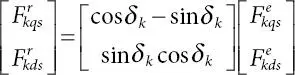
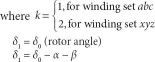
whereas β shows the phase difference between the terminal voltage of phases a and x . Numerically, the numerical value of both α and β is 30° electrical.
The linearized version of above of nonlinear differential equation ( 1.45) with suitable approximation ( cos Δδ k= 1 and sin Δδ k= Δδ k) results in
(1.46) 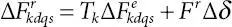
Inverse transformation of above equation yields
(1.47) 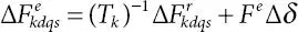
where Fr and Fe represent the d-q performances indices under steady state.
(1.48) 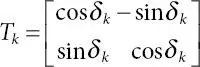
(1.49) 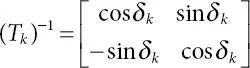
Substituting Equations ( 1.46) and ( 1.47) into Equation ( 1.44) results in
(1.50) 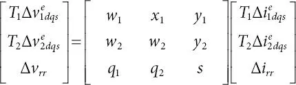
and is rearranged as
(1.51) 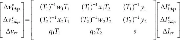
Simplified version of above equation can be written as
(1.52) 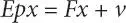
In above expressions, the additional subscript “ 0 ”  represent the value during steady state. Rewriting Equation ( 1.52) in fundamental form
(1.53) 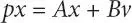
where

In above linearized model of machine, the effect of mutual coupling between stator winding sets abc and xyz is considered (by using mutual leakage reactance, xlm and xldq ). Results are presented in consideration of the asymmetrical six-phase synchronous machine (α = 30° electrical) in comparison with its three-phase equivalent.
1.4 Dynamic Performance Results
Dynamic analysis of any electrical system is of prime importance to understand its operating characteristic under different conditions changing suddenly. Therefore, the mathematical model developed in previous section has been effectively used to analyze the behavior of grid connected six-phase synchronous generator under sudden change in active load. For this purpose, a set of differential equations that describe the synchronous machine operation were simulated in MATLAB/Simulink environment. Simulation has been carried out for a machine of 3.2 kW, 6 poles, whose parameters are mentioned in the Appendix.
Computer traces in Figures 1.2and 1.3are showing the dynamic behavior of six-phase synchronous generator due to a step change in output active power from 0% to 50% of rated/base value at time t = 5 s and further increase in output power by 50% (i.e., at full load) at time t = 15 s. It is assumed that the terminal voltage and frequency is constant irrespective of the change in load torque. Input phase voltage was maintained constant at 240 V, 50 Hz, operating at 0.85 power factor (lagging). Initially, generator is operating at no load condition at synchronous speed. At time t = 5 s, a step increase in output power, and hence, increase in prime mover applied torque Tl is considered. This resulted in the increase in rotor speed immediately, following the step increase in prime mover torque as shown in Figure 1.2a, where the load angle δ increases in Figure 1.2c. The rotor speed continues to increase till the accelerating torque on the rotor vanishes. It can be noted from Figure 1.2bthat the speed increases to approximately 105 rad/sec at the time when Te equal to Tl . At this time, accelerating torque is zero and the rotor is running above synchronous speed; hence, load angle δ, and thus motor torque Te will keep on decreasing. Decrease in torque Te results in decrease in output power of the machine that causes the rotor to decelerate toward synchronous speed. Hence, due to rotor inertia, it will continue to decelerate below synchronous speed, and consequently, load angle δ begins to increase, with increase in generated torque Te . In this way, damped oscillation of machine continues and settles to a new-steady state value.
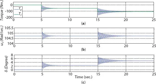
Figure 1.2 Dynamic response of motor following the change in load torque showing (a) motor torque Te , (b) rotor speed ω r, and (c) load angle, delta .
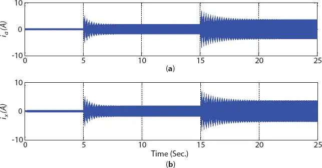
Figure 1.3 Dynamic response of motor following the change in load torque showing stator currents (a) ia and (b) ix.
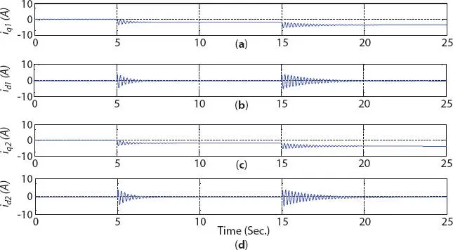
Figure 1.4 d-q component of stator winding currents (a) Iq 1, (b) Id 1, (c) Iq 2, and (d) Id 2.
Due to the increase in generator prime mover input torque, increase in stator phase current can be noted in Figure 1.3, which is required to meet the increased output. The increase in stator current is associated with the increase in active output power of the generator, while maintaining its operation at constant power factor (i.e., constant reactive power). Hence, the change in q -axis component of stator current (active component of current changes from 1.8 A at 50% output power to 3.6 A at rated output, approximately) is depicted in Figure 1.4, with no change in its d -axis component of stator current (reactive component of current), of both the winding sets abc and xyz .
Читать дальшеИнтервал:
Закладка:
Похожие книги на «Artificial Intelligence for Renewable Energy Systems»
Представляем Вашему вниманию похожие книги на «Artificial Intelligence for Renewable Energy Systems» списком для выбора. Мы отобрали схожую по названию и смыслу литературу в надежде предоставить читателям больше вариантов отыскать новые, интересные, ещё непрочитанные произведения.


Обсуждение, отзывы о книге «Artificial Intelligence for Renewable Energy Systems» и просто собственные мнения читателей. Оставьте ваши комментарии, напишите, что Вы думаете о произведении, его смысле или главных героях. Укажите что конкретно понравилось, а что нет, и почему Вы так считаете.