Geophysical Monitoring for Geologic Carbon Storage
Здесь есть возможность читать онлайн «Geophysical Monitoring for Geologic Carbon Storage» — ознакомительный отрывок электронной книги совершенно бесплатно, а после прочтения отрывка купить полную версию. В некоторых случаях можно слушать аудио, скачать через торрент в формате fb2 и присутствует краткое содержание. Жанр: unrecognised, на английском языке. Описание произведения, (предисловие) а так же отзывы посетителей доступны на портале библиотеки ЛибКат.

- Название:Geophysical Monitoring for Geologic Carbon Storage
- Автор:
- Жанр:
- Год:неизвестен
- ISBN:нет данных
- Рейтинг книги:4 / 5. Голосов: 1
-
Избранное:Добавить в избранное
- Отзывы:
-
Ваша оценка:
Geophysical Monitoring for Geologic Carbon Storage: краткое содержание, описание и аннотация
Предлагаем к чтению аннотацию, описание, краткое содержание или предисловие (зависит от того, что написал сам автор книги «Geophysical Monitoring for Geologic Carbon Storage»). Если вы не нашли необходимую информацию о книге — напишите в комментариях, мы постараемся отыскать её.
Geophysical Monitoring for Geologic Carbon Storage
Volume highlights include: Geophysical Monitoring for Geologic Carbon Storage
The American Geophysical Union promotes discovery in Earth and space science for the benefit of humanity. Its publications disseminate scientific knowledge and provide resources for researchers, students, and professionals.
Geophysical Monitoring for Geologic Carbon Storage — читать онлайн ознакомительный отрывок
Ниже представлен текст книги, разбитый по страницам. Система сохранения места последней прочитанной страницы, позволяет с удобством читать онлайн бесплатно книгу «Geophysical Monitoring for Geologic Carbon Storage», без необходимости каждый раз заново искать на чём Вы остановились. Поставьте закладку, и сможете в любой момент перейти на страницу, на которой закончили чтение.
Интервал:
Закладка:
(5.1) 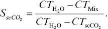
Similarly, fracture apertures can be determined from CT values of intact and fractured samples at the fracture location and of the fluid within the fracture ( CT Intact, CT Fractured, and CT Pore fluid, respectively) (Ketcham et al., 2010). Note that the intact sample measurement can be substituted by the CT values of the rock matrix near the fracture, if the sample is reasonably homogeneous. For this case, the fracture aperture is computed by
(5.2) 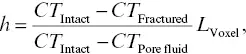
where L Voxelis the dimension of the voxel in the image.
Ideally, the CT‐indicated density of the scCO 2‐saturated case would also be used for saturation computations. However, because exposure of the dry rock to scCO 2has been observed to affect the rock wettability (McCool & Tripp, 2005) and thus scCO 2invasion, the scCO 2‐saturated case was estimated by interpolating between the CT‐indicated density numbers of the water‐saturated and dry cases based on the relative densities of the water and scCO 2. This approach is generally effective where the spatial scale of the CT noise is smaller than the spatial scale of the features of interest. For CO 2saturation in a fracture where the spatial scale of noise is larger than the fracture aperture, a segmentation approach was used in which the location of the fracture aperture was determined from the dry set of scans, and computations of differences were performed on those specific locations separately.
5.2.3. Samples and Test Cases
A series of seismic measurements with X‐ray CT imaging was conducted on two Carbon Tan sandstone core samples (Kocurek Industries, Inc., http://www.kocurekindustries.com/) with various fracture configurations ( Table 5.1). The sandstone has a porosity of 16.7% and a matrix permeability of 34.5 md (measured only for the Carbon Tan #2 core. However, similar dry densities of the #1 and #2 cores (2,380 kg/m 3and 2,375 kg/m 3, respectively) indicate that the #1 core has a similar porosity. The permeability was measured using the falling‐head permeability test method (e.g., Head, 1982) under unconfined conditions, using tap water at room temperature. The diameter of the cores was 38 mm, and the length varied slightly among the cores, from 98 mm to 101 mm. A single fracture was introduced in each core via extensile splitting (Brazilian loading) either parallel or perpendicular to the core axis.
Table 5.1 Descriptions of test samples with different fracture configurations
| Sample | Description | scCO 2injection rate (mL/min) | Configuration | |
|---|---|---|---|---|
Carbon Tan #1 core 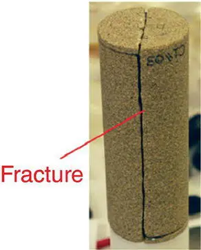 |
Intact I | Intact core | 0.035 | 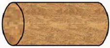 |
| Frac Ia | Mated core‐parallel fracture (no offset) | 0.037 | 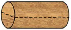 |
|
| Frac Ib | Sheared core‐parallel fracture; with spacers | 0.017 | 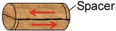 |
|
| Frac Ic | Sheared core‐parallel fracture; without spacers (shorter core) | 0.027 | 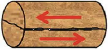 |
|
| Frac Id | Same as Frac Ic sample, but with a vertically oriented fracture | 0.043 | 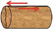 |
|
Carbon Tan #2 core 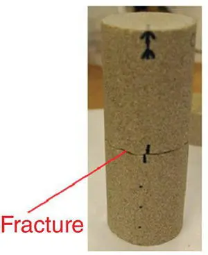 |
Intact II | Intact core | 0.042 | 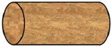 |
| Frac IIa | Sheared (rotationally offset) core‐perpendicular fracture; with a mylar wrapping | 0.023 | 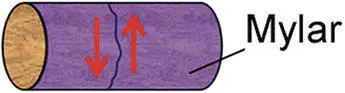 |
|
| Frac IIb | Sheared (rotationally offset) core‐perpendicular fracture | 0.020 | 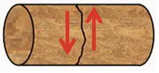 |
Note: The core numbers were redesignated in this paper and can be different from what are seen in the photographs.
The first core sample (Carbon Tan #1) was tested for: intact state (Intact I); a mated, core‐parallel fracture (Frac Ia); a sheared (linearly displaced) core‐parallel fracture with end spacers (Frac Ib); and a sheared core parallel fracture without end spacers (Frac Ic). The end spacers (thickness 3 mm) in the Frac Ib test, which were coupled to the sample and the metal rods using thin lead foil disks, were made from the same sandstone and were used to apply and maintain a shear offset along the fracture surface. These spacers were later removed, and the protruding sample ends were ground flat for use in the Frac Ic test. These tests were all conducted while the fracture was oriented horizontally. In addition, the same test as Frac Ic was conducted while the fracture was oriented vertically to examine the effect of buoyancy‐controlled scCO 2migration within the fracture on seismic waves (Frac Id).
For the second core sample (Carbon Tan #2), tests were conducted for: intact state (Intact II); a sheared (rotational offset) core‐perpendicular fracture with a Mylar wrapping (Frac IIa); and the same sample as Frac IIa without the Mylar wrapping (Frac IIb). Note that for Frac IIa test, scCO 2followed a preferential flow path along the Mylar sheet, resulting in premature breakthrough across the core. This test can be viewed as a special case where both core‐perpendicular and core‐parallel fractures are present. However, the permeability of this fast‐pass‐providing core‐parallel “fracture” was thought to be small.
5.2.4. Determination of Elastic Moduli and Attenuation From Measured Resonances
SHRB measurements determine dynamic Young's modulus E , shear modulus G , and their related attenuations (vibration damping factors) a Eand a Grespectively (given by 1/2 Q Eand 1/2 Q Gusing the seismic quality factors). Note that for anisotropic rock, E is the longitudinal modulus along the core axis, and G is the torsion modulus around the core axis. During an experiment, fundamental‐mode resonances of both longitudinal‐mode vibration and torsional‐mode vibration are measured, using combinations of longitudinal piezoelectric source and the axial accelerometer, and of the torsional source and the tangential accelerometers, respectively. For each resonance, its peak frequency f cand the half‐power width Δf are measured. From these values, the quality factor of the resonance is obtained by Q –1=Δ f / f c. In our experiments, f cand a= 1/2 Q values are measured and computed automatically by the spectrum analyzer.
Читать дальшеИнтервал:
Закладка:
Похожие книги на «Geophysical Monitoring for Geologic Carbon Storage»
Представляем Вашему вниманию похожие книги на «Geophysical Monitoring for Geologic Carbon Storage» списком для выбора. Мы отобрали схожую по названию и смыслу литературу в надежде предоставить читателям больше вариантов отыскать новые, интересные, ещё непрочитанные произведения.


Обсуждение, отзывы о книге «Geophysical Monitoring for Geologic Carbon Storage» и просто собственные мнения читателей. Оставьте ваши комментарии, напишите, что Вы думаете о произведении, его смысле или главных героях. Укажите что конкретно понравилось, а что нет, и почему Вы так считаете.