Umashankar Subramaniam - Smart Grids and Micro-Grids
Здесь есть возможность читать онлайн «Umashankar Subramaniam - Smart Grids and Micro-Grids» — ознакомительный отрывок электронной книги совершенно бесплатно, а после прочтения отрывка купить полную версию. В некоторых случаях можно слушать аудио, скачать через торрент в формате fb2 и присутствует краткое содержание. Жанр: unrecognised, на английском языке. Описание произведения, (предисловие) а так же отзывы посетителей доступны на портале библиотеки ЛибКат.
- Название:Smart Grids and Micro-Grids
- Автор:
- Жанр:
- Год:неизвестен
- ISBN:нет данных
- Рейтинг книги:5 / 5. Голосов: 1
-
Избранное:Добавить в избранное
- Отзывы:
-
Ваша оценка:
Smart Grids and Micro-Grids: краткое содержание, описание и аннотация
Предлагаем к чтению аннотацию, описание, краткое содержание или предисловие (зависит от того, что написал сам автор книги «Smart Grids and Micro-Grids»). Если вы не нашли необходимую информацию о книге — напишите в комментариях, мы постараемся отыскать её.
Written and edited by a team of experts in the field, this is the most comprehensive and up-to-date study of smart grids and microgrids for engineers, scientists, students, and other professionals.
Audience:
Smart Grids and Micro-Grids — читать онлайн ознакомительный отрывок
Ниже представлен текст книги, разбитый по страницам. Система сохранения места последней прочитанной страницы, позволяет с удобством читать онлайн бесплатно книгу «Smart Grids and Micro-Grids», без необходимости каждый раз заново искать на чём Вы остановились. Поставьте закладку, и сможете в любой момент перейти на страницу, на которой закончили чтение.
Интервал:
Закладка:
a. If the system is in grid-connected mode, the VSI is supposed to supply real and reactive power to the grid. In case the ESS is discharged, ac power has to be absorbed from the grid to charge the ESS.
b. In islanded mode, the ESS is required to maintain the PCC voltage to the reference voltage.
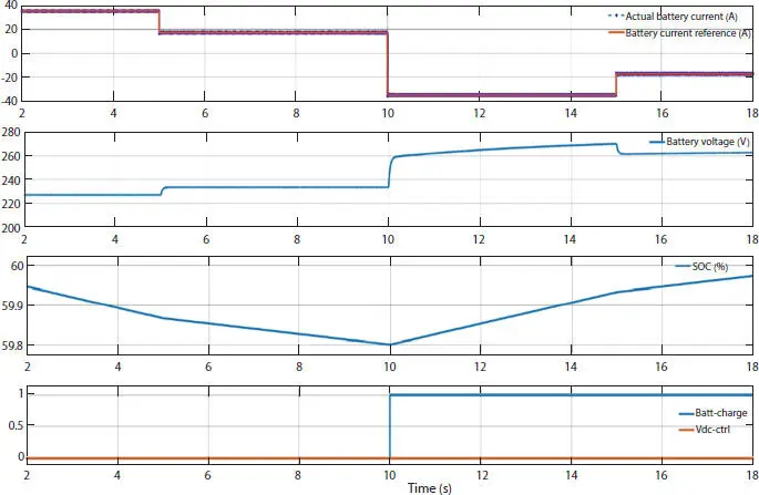
Figure 2.5 Waveforms under the condition when battery-converter system is connected to microgrid.
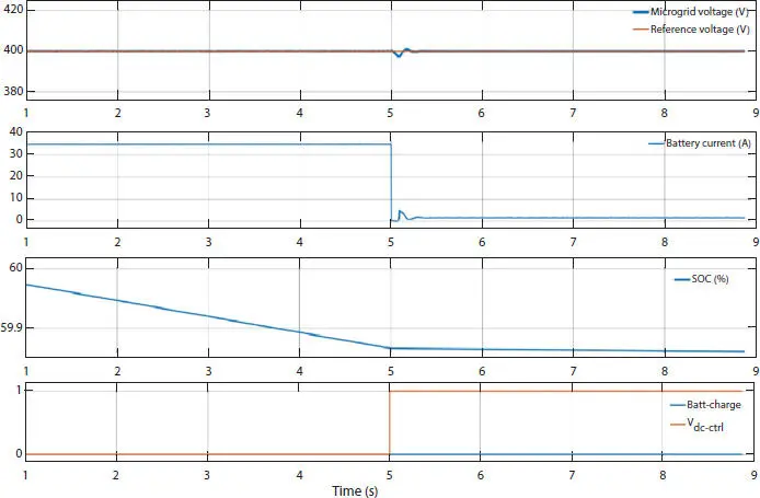
Figure 2.6 Waveforms under the condition when battery-converter system is in islanded mode.
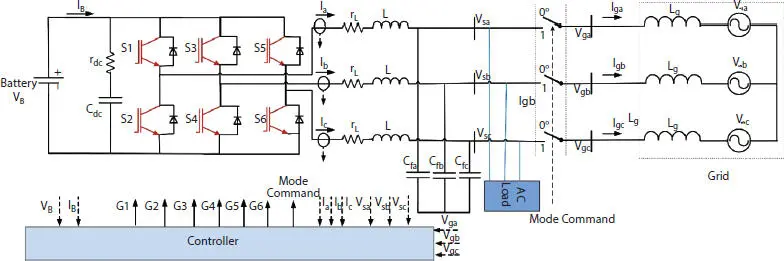
Figure 2.7 Three-phase inverter interfacing battery to grid.
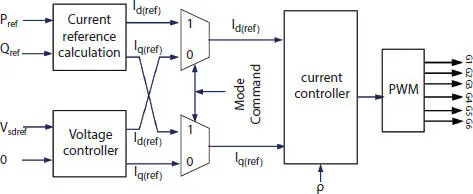
Figure 2.8 Controller for inverter interfacing battery to grid.
In order to address the above requirements, the controller should have a provision to work under the mode dictated by EMS. One typical configuration of such a controller is shown in Figure 2.8. For an AC system, the variables to be regulated are a sinusoidal function of time and hence the closed-loop control system must have a sufficiently large bandwidth for tracking the variables. To transform variables to dc quantities for achieving zero steady-state error by using a PI controller and decoupling the regulation of real power and reactive power, the converter is controlled in the synchronous frame (d-q) [14].
When Mode command= 1 (the converter is in grid-connected mode), the battery is supposed to supply active or reactive power to the grid. The reference power ( P ref, Q ref) that has to be supplied by the battery-converter system is obtained from the energy management system of the microgrid. The instantaneous active ( P ) and reactive powers ( Q ) supplied by the converter system can be expressed in a d-q frame as
(2.17) 
(2.18) 
Where V s, i d, and i qare PCC voltage on d-axis, output current on d-axis, and output current on q-axis, respectively. As the grid-connected converter act as current source, the reference grid current ( i d(ref), i q(ref)) to be fed can be obtained using relation
(2.19) 
(2.20) 
The inner current loop is designed to track the reference current ( id (ref) , i q(ref)) and it generates the PWM gating signal for switches of the converter. The current loop needs angle ρ ( to convert quantities from the d-q frame back to abc frame) information, which is obtained from the Phase-locked loop of the system. When the battery SOC is low, then the reference active power is negative ( P ref= -ve and Q ref= 0) to charge the battery.
When Mode command= 0, the microgrid is in islanded mode and the voltage at PCC has to be regulated to a reference voltage. The battery is supposed to supply active or reactive power to the grid to maintain the PCC voltage. The current reference ( ( i d(ref), i q(ref)) is obtained from an outer voltage loop. The outer voltage loop ensures that the PCC voltage is maintained at its reference value. The modeling of the converter and design of the controller under different modes is discussed in the next section.
2.5.2.1 Modelling and Control of the VSI
The AC voltage of the PCC is expressed as
(2.21) 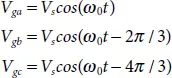
Applying Kirchhoff ’s voltage equation in the phase, we get
(2.22) 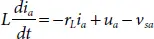
(2.23) 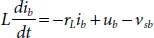
(2.24) 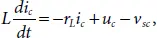
To transfer the above system to synchronous reference frame, the following transformation need to be performed
(2.25) 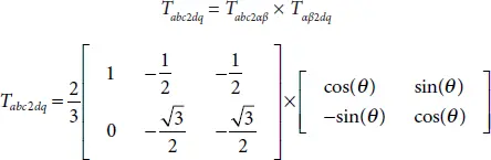
Where T abc2αβ, T αβ2dqand θ are known as Clark transformation, Park transformation, and the phase angle of the grid which is obtained from PLL, respectively. The resulting system after transformation is given by
(2.26) 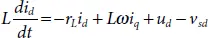
(2.27) 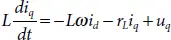
Where v sd, u dand i dare PCC voltage, VSC output voltage and output current on d-axis, respectively. u qand i qare VSC output voltage and output current on the q-axis, respectively. One can notice from equation (2.26)and (2.27)that the system is converted to an LTI system having some coupling states. A simple control law to decouple the term is given by
(2.28) 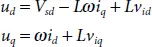
Where v idand v iqare the feedback control input. for obtaining zero steady-state error, PI controller is applied to control input
(2.29) 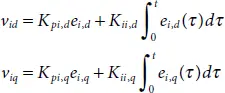
Where e id= ( i d(ref)– i d), e iq= ( i q(ref)– i q), K pi,d, K ii,d, K pi,qand K ii,qare parameters/gains of PI controller for d-axis current and q-axis current controller. Since the system model is LTI, it can be easily analysed and the current controller can be easily designed using linear control techniques.
For the case when the microgrid in islanded mode, the converter has to regulate the voltage at PCC. By applying Kirchhoff’s law at the PCC voltage and applying the d-q transform on the resulting equations, one would obtain
Читать дальшеИнтервал:
Закладка:
Похожие книги на «Smart Grids and Micro-Grids»
Представляем Вашему вниманию похожие книги на «Smart Grids and Micro-Grids» списком для выбора. Мы отобрали схожую по названию и смыслу литературу в надежде предоставить читателям больше вариантов отыскать новые, интересные, ещё непрочитанные произведения.


Обсуждение, отзывы о книге «Smart Grids and Micro-Grids» и просто собственные мнения читателей. Оставьте ваши комментарии, напишите, что Вы думаете о произведении, его смысле или главных героях. Укажите что конкретно понравилось, а что нет, и почему Вы так считаете.