Umashankar Subramaniam - Smart Grids and Micro-Grids
Здесь есть возможность читать онлайн «Umashankar Subramaniam - Smart Grids and Micro-Grids» — ознакомительный отрывок электронной книги совершенно бесплатно, а после прочтения отрывка купить полную версию. В некоторых случаях можно слушать аудио, скачать через торрент в формате fb2 и присутствует краткое содержание. Жанр: unrecognised, на английском языке. Описание произведения, (предисловие) а так же отзывы посетителей доступны на портале библиотеки ЛибКат.
- Название:Smart Grids and Micro-Grids
- Автор:
- Жанр:
- Год:неизвестен
- ISBN:нет данных
- Рейтинг книги:5 / 5. Голосов: 1
-
Избранное:Добавить в избранное
- Отзывы:
-
Ваша оценка:
Smart Grids and Micro-Grids: краткое содержание, описание и аннотация
Предлагаем к чтению аннотацию, описание, краткое содержание или предисловие (зависит от того, что написал сам автор книги «Smart Grids and Micro-Grids»). Если вы не нашли необходимую информацию о книге — напишите в комментариях, мы постараемся отыскать её.
Written and edited by a team of experts in the field, this is the most comprehensive and up-to-date study of smart grids and microgrids for engineers, scientists, students, and other professionals.
Audience:
Smart Grids and Micro-Grids — читать онлайн ознакомительный отрывок
Ниже представлен текст книги, разбитый по страницам. Система сохранения места последней прочитанной страницы, позволяет с удобством читать онлайн бесплатно книгу «Smart Grids and Micro-Grids», без необходимости каждый раз заново искать на чём Вы остановились. Поставьте закладку, и сможете в любой момент перейти на страницу, на которой закончили чтение.
Интервал:
Закладка:
(2.3) 
The current compensator is given by
(2.4) 
Where k p, iand k i, iare gain of PI controller of current loop. The control system loop gain is
(2.5) 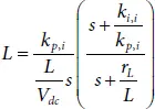
For improving the open-loop frequency response, the pole can be canceled by the zero of the PI compensator. Defining τ iis the desired time constant of the closed-loop system (  is the bandwidth of the current closed-loop), we can choose
(2.6) 
(2.7) 
As discussed earlier, sometimes the dc-dc converter is supposed to control the output voltage, i.e., dc microgrid voltage. To derive the transfer function between the output voltage and inductor current which would be the outer control loop of the converter, let the perturbation in output voltage be  . Using the perturbations in equation (2.1)and linearizing the resulting expressing, one would obtain
(2.8) 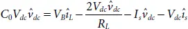
The transfer function from output voltage to inductor current of the outer loop is given by
(2.9) 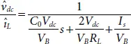
The voltage compensator is given by
(2.10) 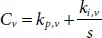
Where kp,v and ki,v are gain of PI controller of voltage loop. The control system loop gain is
(2.11) 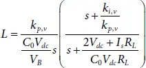
As stated earlier, the pole can be eleminated by the zero of the PI compensator. Defining τ vis the desired time constant of the closed-loop system (  is the bandwidth of the voltage closed loop), we can choose
(2.12) 
(2.13) 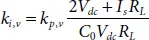
The current loop is designed with a crossover frequency of less than a tenth of the switching frequency of the converter. The voltage compensator is designed to have the crossover frequency to be one half of the crossover frequency of the current loop [11].
2.5.1.2 Typical Case Study in MATLAB-Simulink
A MATLAB-Simulink model of the converter system shown in Figure 2.2is developed with the specification listed in Table 2.3. The controller shown in Figure 2.3for control of the bidirectional converter is also implemented in the Simulink platform. The components of the dc-dc converter are selected based using relations [12, 13].
(2.14) 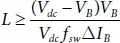
(2.15) 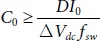
(2.16) 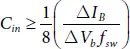
Where V B, I Bare battery voltage and battery current, respectively while Δ V B, Δ I Bare the ripple in the battery. f sw, V dcare switching frequency and microgrid dc voltage, respectively. The commands “ Batt – charge , V dc–ctrl” along with the power to be exchanged ( I B(disc, ref), I B(cha, ref)) with microgird are sent to the controller from the EMS of microgrid. The feedback signals inductor current ( i L), dc microgrid voltage ( V dc) are also input to the controller.
Table 2.3 Specifications of the boost converter interfacing dc microgrid and battery.
| Parameter | Value |
| Nominal voltage ( V B) | 240 V |
| Rated capacity | 35 Ah |
| Initial SOC | 60% |
| Inductance ( L ) ESR ( r L) of inductor | 2.6 mH 0.005Ω |
| Output capacitor ( C 0) | 2200 µF |
| DC load | 400 Ω |
| DC microgrid voltage | 400 V |
Figure 2.5shows the results for the case when V dc–ctrl= 0, i.e., ESS should be charging or discharging depending on the status of the Batt – charge command. Initially, command V dc–ctrl= 1, and the battery discharging current reference is set to 35 A. After 5 sec, the discharging current reference is changed to 17.5 A. After 10 sec, command Batt – charge = 1 and the reference of charging current is kept at 35 A, which was subsequently changed to 17.5 A at 15 sec. The controller was able to track the reference current, as evident from the waveform of Figure 2.5. It is also clear from the figure that the SOC was decreasing when the battery was discharging, while SOC was increasing for the case when the battery was discharging. A similar observation can be made about the battery voltage.
For the case, when it is required to maintain the dc voltage level of microgrid, the command V dc–ctrl= 1 is received from the microgrid. The reference for dc microgrid voltage is set to 400V. To show the performance of controller under such condition, initially V dc–ctrl= 0, Batt – charge = 0 and the battery discharging current reference ( I B(disc, ref)was set to 35 A. At t=5 sec, the V dc–ctrl= 1 was sent to the controller. Figure 2.6shows the performance of the controller. It shows that the converter was able to track the reference voltage.
2.5.2 DC-AC VSI Interfacing AC-Microgrid
Depending on microgrid structure, grid-tied inverter interfaces the ESS (Energy Storage Systems) to the external ac gird or the ac bus of ac microgrid. Generally, 3-phase VSI based converter is used and a typical schematic is shown in Figure 2.7. The converter and its associated controller is supposed to perform the following functions:
Читать дальшеИнтервал:
Закладка:
Похожие книги на «Smart Grids and Micro-Grids»
Представляем Вашему вниманию похожие книги на «Smart Grids and Micro-Grids» списком для выбора. Мы отобрали схожую по названию и смыслу литературу в надежде предоставить читателям больше вариантов отыскать новые, интересные, ещё непрочитанные произведения.


Обсуждение, отзывы о книге «Smart Grids and Micro-Grids» и просто собственные мнения читателей. Оставьте ваши комментарии, напишите, что Вы думаете о произведении, его смысле или главных героях. Укажите что конкретно понравилось, а что нет, и почему Вы так считаете.