Umashankar Subramaniam - Smart Grids and Micro-Grids
Здесь есть возможность читать онлайн «Umashankar Subramaniam - Smart Grids and Micro-Grids» — ознакомительный отрывок электронной книги совершенно бесплатно, а после прочтения отрывка купить полную версию. В некоторых случаях можно слушать аудио, скачать через торрент в формате fb2 и присутствует краткое содержание. Жанр: unrecognised, на английском языке. Описание произведения, (предисловие) а так же отзывы посетителей доступны на портале библиотеки ЛибКат.
- Название:Smart Grids and Micro-Grids
- Автор:
- Жанр:
- Год:неизвестен
- ISBN:нет данных
- Рейтинг книги:5 / 5. Голосов: 1
-
Избранное:Добавить в избранное
- Отзывы:
-
Ваша оценка:
Smart Grids and Micro-Grids: краткое содержание, описание и аннотация
Предлагаем к чтению аннотацию, описание, краткое содержание или предисловие (зависит от того, что написал сам автор книги «Smart Grids and Micro-Grids»). Если вы не нашли необходимую информацию о книге — напишите в комментариях, мы постараемся отыскать её.
Written and edited by a team of experts in the field, this is the most comprehensive and up-to-date study of smart grids and microgrids for engineers, scientists, students, and other professionals.
Audience:
Smart Grids and Micro-Grids — читать онлайн ознакомительный отрывок
Ниже представлен текст книги, разбитый по страницам. Система сохранения места последней прочитанной страницы, позволяет с удобством читать онлайн бесплатно книгу «Smart Grids and Micro-Grids», без необходимости каждый раз заново искать на чём Вы остановились. Поставьте закладку, и сможете в любой момент перейти на страницу, на которой закончили чтение.
Интервал:
Закладка:
AC-DC converter (rectifier) converts AC input power into DC output power. The rectifier provides DC power to charge the BESS. Three-phase rectifiers are widely used for the industrial, electrical transportation system and the transmission of energy applications. Moreover, a DC-AC converter (inverter) is a crucial device that connects any DC power source to an AC bus in the power system. Inverters appeared as a promising power converter with numerous medium and high-power applications such as industrial motor drives, variable-frequency drives, EV/HEV, UPS, grid-connected renewable energy sources, HVDC, flexible AC transmission system. The typical inverters and rectifiers model are similar, which allows the converter to operate as either a rectifier or an inverter.
2.4.3 AC-AC Converter
AC to AC converter is utilized to convert the AC to another AC with requisite frequency and magnitude. AC to AC converter is mainly classified as cycle converters, Indirect AC to AC converter (DC- Link converter), matrix Converters and hybrid matrix converter. AC to AC converter is used for speed control of drive, the interconnection of AC buses and charging and discharging of ESS.
2.5 Control of Interfaced Converters
The role of the control and management system in a microgrid is indispensable in addition to the design of converters. The ESS in the microgrid requires a bidirectional power flow for its charging and discharging, which is possible by controlling the required converters. The control of charging and discharging process of ESS for Ac and Dc microgrid is explained in the following section.
2.5.1 DC-DC Bidirectional Converter Interfacing DC-Microgrid
In order to exchange power with the dc microgrid or dc link of the microgrid circuit from ESS, a DC-DC bidirectional converter is required. Depending on the voltage of the microgrid and battery, a different configuration of DC-DC could be used. As an example, Figure 2.2shows a bidirectional boost converter interfacing battery to the DC system or DC-link of the DC-AC converter. Based on the requirement of the microgrid, the following condition could arise:
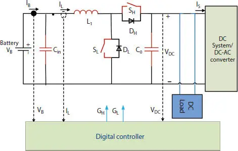
Figure 2.2 Boost converter interfacing battery to dc microgrid.
1 a. ESS (Energy Storage Systems) may be required to discharge if the energy management system (EMS) of the microgrid needs power from the ESS
2 b. If ESS is discharged or there is excess power from the other distributed energy sources, the ESS is supposed to be charged.
3 c. In case the dc microgrid voltage deviates from its reference value and other ESS in the system fails to maintain the microgrid voltage owing to a low state of charge (SOC), the ESS with a considerable amount of capacity left has to control the microgrid voltage.
To fulfill the above objective/role of the ESS, the converter controller should have the provision of working in all the modes as dictated by EMS. One typical configuration of such a controller is shown in Figure 2.3. The signal Batt – charge , I B(cha, ref), I B(disc, ref), V dc-ctrlare provided by the EMS depending on the requirement of the microgrid. When battery has to be discharged, command Batt – charge = 0, V dc-ctrl= 0 and reference battery discharge reference current ( I B(cha, ref)) is received from EMS. The current loop is activated where reference current is compared to battery current to produce error signal which is sent to PI controller to produce PWM. Since the current has to be supplied by the ESS, the bottom switch ( S L) has to be modulated and the gating signal of the top switch ( S H) has to be disabled. This is achieved by multiplying the PWM signal with the Batt – charge command to ensures that the proper gating signal is sent to the converter. If Batt – charge = 1, V dc-ctrl= 0 and reference battery charge reference current ( I B(cha, ref)) is received from EMS, it implies that battery has to be charged. This requires that the top switch ( S H) has to be modulated and the bottom diode ( D L) would be working. The Batt – charge = 1, multiplied with PWM produces the top switch gating signal ( G H) for the top switch and turns-off the bottom gating signal ( G L= 0).
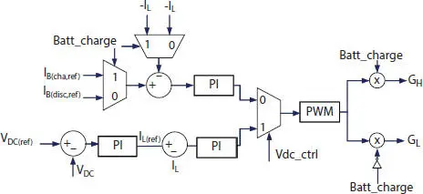
Figure 2.3 Typical configuration of the controller.
The signal V dc-ctrl= 1 from EMS implies that the battery is required to maintain the dc voltage of the microgrid. There are two loops in control to have the fast dynamic response of the system. The outer voltage loop compares the reference voltage to the voltage of the microgrid. The error signal is passed through the PI controller to produce the reference current. This reference current is compared with the inductor current to generate an error, which is fed to PI to produce a duty cycle. When the dc-microgrid voltage ( V DC) is lower than the reference microgrid voltage ( V DC(ref)), the comparator produces a positive error, which results in an increase in the reference inductor current ( IL(ref)) ) driving more current to microgrid and thereby increasing the dc voltage of the microgrid. Similarly, when the dc-microgrid voltage ( V DC) is higher than the reference microgrid voltage ( V DC(ref)), the voltage comparator produces a negative error, which results in decrease in reference inductor current ( I L(ref)). This results in decrease in the current supplied by the battery-converter system, thereby resulting in decrease in the dc-microgrid voltage. The PWM module produces the gating signal for the switches. The modeling of converter and design of the control loop under different modes is discussed in the next section.
2.5.1.1 Modeling and Control of the Converter
The equivalent circuit of the boost converter is shown in Figure 2.4. V Band i Bare the battery voltage and curent, respectively. Applying Kirchhoff’s Voltage Law (KVL) in the inductor loop and Kirchhoff’s current law at the node C ingives,
(2.1) 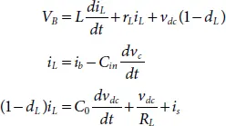
The instantaneous state-space variable vector can be written as,
(2.2) 
Where I Land D Lrepresent the DC values of input current (= I B) and duty cycle of the lower switch, respectively, and î Land  represent the perturbation values of input current and duty cycle, respectively. During the charge and discharge mode of the battery, the output voltage ( V dc) and battery voltage ( V B) can be assumed to be constant. Equations (2.1)and (2.2)can be used to obtain the transfer function between input current and duty cycle as
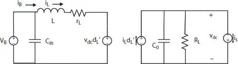
Figure 2.4 Equivalent circuit of the converter.
Читать дальшеИнтервал:
Закладка:
Похожие книги на «Smart Grids and Micro-Grids»
Представляем Вашему вниманию похожие книги на «Smart Grids and Micro-Grids» списком для выбора. Мы отобрали схожую по названию и смыслу литературу в надежде предоставить читателям больше вариантов отыскать новые, интересные, ещё непрочитанные произведения.


Обсуждение, отзывы о книге «Smart Grids and Micro-Grids» и просто собственные мнения читателей. Оставьте ваши комментарии, напишите, что Вы думаете о произведении, его смысле или главных героях. Укажите что конкретно понравилось, а что нет, и почему Вы так считаете.