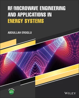
Abdullah Eroglu - RF/Microwave Engineering and Applications in Energy Systems
Здесь есть возможность читать онлайн «Abdullah Eroglu - RF/Microwave Engineering and Applications in Energy Systems» — ознакомительный отрывок электронной книги совершенно бесплатно, а после прочтения отрывка купить полную версию. В некоторых случаях можно слушать аудио, скачать через торрент в формате fb2 и присутствует краткое содержание. Жанр: unrecognised, на английском языке. Описание произведения, (предисловие) а так же отзывы посетителей доступны на портале библиотеки ЛибКат.
- Название:RF/Microwave Engineering and Applications in Energy Systems
- Автор:
- Жанр:
- Год:неизвестен
- ISBN:нет данных
- Рейтинг книги:5 / 5. Голосов: 1
-
Избранное:Добавить в избранное
- Отзывы:
-
Ваша оценка:
- 100
- 1
- 2
- 3
- 4
- 5
RF/Microwave Engineering and Applications in Energy Systems: краткое содержание, описание и аннотация
Предлагаем к чтению аннотацию, описание, краткое содержание или предисловие (зависит от того, что написал сам автор книги «RF/Microwave Engineering and Applications in Energy Systems»). Если вы не нашли необходимую информацию о книге — напишите в комментариях, мы постараемся отыскать её.
An essential text with a unique focus on RF and microwave engineering theory and its applications RF/Microwave Engineering and Applications in Energy Systems,
RF/Microwave Engineering and Applications in Energy Systems
RF/Microwave Engineering and Applications in Energy Systems — читать онлайн ознакомительный отрывок
Ниже представлен текст книги, разбитый по страницам. Система сохранения места последней прочитанной страницы, позволяет с удобством читать онлайн бесплатно книгу «RF/Microwave Engineering and Applications in Energy Systems», без необходимости каждый раз заново искать на чём Вы остановились. Поставьте закладку, и сможете в любой момент перейти на страницу, на которой закончили чтение.
Интервал:
Закладка:
8 Chapter 8Figure 8.1 Ideal filter characteristics.Figure 8.2 Filter design block diagram.Figure 8.3 Attenuation profiles of a low pass filter.Figure 8.4 Two‐port network representation.Figure 8.5 Transfer function analysis circuits: (a) low pass filter; (b) hig...Figure 8.6 Transfer function analysis circuits: (a) bandpass filter; (b) ban...Figure 8.7 Network analysis of (a) low pass filter and (b) high pass filter....Figure 8.8 Insertion loss for low pass filter when C = 8 pF, R = 100 Ω, and Figure 8.9 Low pass filter simulation when C = 8 pF, R = 100 Ω, and Z o= 50 ...Figure 8.10 Simulated insertion loss for low pass filter when C = 8 pF, R = ...Figure 8.11 Insertion loss for high pass filter when L = 5 nH, R = 5 Ω, and Figure 8.12 Network analysis of (a) bandpass filter and (b) bandstop filter....Figure 8.13 Insertion loss for bandpass filter when L = 6 nH, C = 1 pF, R = ...Figure 8.14 Insertion loss for bandstop filter when L = 2 nH, C = 3 pF, R = ...Figure 8.15 Return loss for bandstop filter when L = 2 nH, C = 3 pF, R = 300...Figure 8.16 Two element low pass prototype circuit.Figure 8.17 Low pass prototype ladder networks (a) 1st element shunt C and (...Figure 8.18 Attenuation curves for binomial filter response for low pass pro...Figure 8.19 Fourth‐order normalized LPF for binomial response.Figure 8.20 Final LPF with binomial response.Figure 8.21 MATLAB results for fourth‐order LPF with binomial response.Figure 8.22 Simulated fourth‐order LPF.Figure 8.23 Simulation results for fourth‐order LPF.Figure 8.24 Attenuation curves for Chebyshev filter response for 0.01 dB rip...Figure 8.25 Attenuation curves for Chebyshev filter response for 0.1 dB ripp...Figure 8.26 Attenuation curves for Chebyshev filter response for 0.5 dB ripp...Figure 8.27 Attenuation curves for Chebyshev filter response for 1 dB ripple...Figure 8.28 Attenuation curves for Chebyshev filter response for 3 dB ripple...Figure 8.29 Fifth‐order normalized LPF for Chebyshev response.Figure 8.30 Final LPF with Chebyshev response.Figure 8.31 Passband ripple response for fifth‐order LPF with Chebyshev filt...Figure 8.32 Attenuation response for fifth‐order LPF with Chebyshev filter r...Figure 8.33 Simulated fifth‐order LPF.Figure 8.34 Simulation results for fifth‐order LPF.Figure 8.35 Input impedance of fifth‐order LPF.Figure 8.36 LPF component to HPF component transformation.Figure 8.37 LPF Prototype circuit to HPF transformation.Figure 8.38 Final HPF filter.Figure 8.39 Attenuation response for fifth‐order HPF.Figure 8.40 Simulated fifth‐order HPF.Figure 8.41 Simulation results for fifth‐order LPF.Figure 8.42 LPF component to BPF component transformation.Figure 8.43 LPF prototype circuit to BPF transformation.Figure 8.44 Attenuation response for four‐section BPF.Figure 8.45 Simulated four‐section BPF.Figure 8.46 Simulation results for four‐section BPF.Figure 8.47 LPF component to BSF component transformation.Figure 8.48 Transmission line model.Figure 8.49 T network equivalent circuit.Figure 8.50 T network representation with transmission lines.Figure 8.51 (a) High impedance transformation of T network; (b) low impedanc...Figure 8.52 Three‐section SIR bandpass filter.Figure 8.53 Triple band bandpass filter using SIR bandpass filters.Figure 8.54 Coupling schemes: (a) improved coupling scheme; (b) conventional...Figure 8.55 Equivalent circuit of parallel coupled lines.Figure 8.56 General setup for implementation of a microstrip edge‐coupled ba...Figure 8.57 Low pass prototype circuit for bandpass filter.Figure 8.58 Bandpass filter with final lumped element component values.Figure 8.59 Bandpass filter simulation results with Ansoft Designer.Figure 8.60 Bandpass filter simulation results with MATLAB.Figure 8.61 Simulated edge‐coupled microstrip circuit with Sonnet.Figure 8.62 Edge‐coupled bandpass filter simulation results with Sonnet.Figure 8.63 End‐coupled microstrip bandpass filter.Figure 8.64 Capacitive‐gap equivalent circuit.Figure 8.65 Layout of microstrip gap for Sonnet simulation.Figure 8.66 Low pass filter prototype.Figure 8.67 Equivalent circuit bandpass filter.Figure 8.68 Equivalent bandpass filter schematic.Figure 8.69 Insertion loss of the equivalent bandpass filter.Figure 8.70 Cg vs. gap length from simulation.Figure 8.71 Cp vs. gap length from simulation.Figure 8.72 Simulation of end‐coupled microstrip bandpass filter.Figure 8.73 Simulation results for end‐coupled microstrip bandpass filter us...Figure 8.74 (a) Typical tapped combline filter; (b) tapped combline equivale...Figure 8.75 Microstrip layout of circuit.Figure 8.76 Transmission line equivalent circuit.Figure 8.77 Network representation of circuit: (a) the two sets of coupled l...Figure 8.78 General coupled line case where the lines are excited from a com...Figure 8.79 Overall excitation circuit for even‐ and odd‐mode analysis.Figure 8.80 Even‐mode excitation circuit.Figure 8.81 Odd‐mode excitation circuit.Figure 8.82 CRLH TLs: (a) unit cell RH TL; (b) unit cell left‐handed transmi...Figure 8.83 Seventh‐order normalized LPF for Chebyshev response.Figure 8.84 Attenuation response of seventh‐order Chebyshev LPF.Figure 8.85 Simulated seventh‐order Chebyshev LPF.Figure 8.86 Simulation result for seventh‐order Chebyshev LPF with 0.5 dB ri...Figure 8.87 Attenuation profile for step impedance filter.Figure 8.88 Simulated step impedance LPF structure.Figure 8.89 Simulation results for step impedance LPF structure with Sonnet....Figure 8.90 Step impedance filter is implemented.Figure 8.91 Measured results for step impedance filter.Figure 8.92 Layout of the triple band bandpass filter.Figure 8.93 The constructed triple band tri‐section bandpass filter using SI...Figure 8.94 Measured and simulation results for insertion loss and return lo...Figure 8.95 Filter performance in the first frequency band.Figure 8.96 Filter performance in the second frequency band.Figure 8.97 Filter performance in the third frequency band.Figure 8.98 Coupling effect between SIR bandpass filters on insertion loss u...Figure 8.99 Effect of coupling in the first frequency band for tri‐section t...Figure 8.100 Effect of coupling in the second frequency band for tri‐section...Figure 8.101 Effect of coupling in the third frequency band for tri‐section ...Figure 8.102 Coupling effect between SIR bandpass filters for return loss up...Figure 8.103 MATLAB GUI to calculate design parameters.Figure 8.104 Dual band bandpass filter using CRLH TLs.Figure 8.105 PCB layout.Figure 8.106 Filter prototype.Figure 8.107 Sixty‐mil FR4 bandpass, S 21(red line), S 11(blue line).Figure 8.108 One‐mil Pyralux bandpass, S 21(red line), S 11(blue line).Figure 8.109 Measurement setup for filter response.Figure 8.110 Sixty‐mil FR4 bandpass insertion loss.Figure 8.111 Design Challenge 8.1.
9 Chapter 9Figure 9.1 Geometry of the rectangular waveguide.Figure 9.2 Geometry of the rectangular waveguide filled with transversely ma...Figure 9.3 Frequency response of the propagation constant for TE mnmodes.Figure 9.4 Permeability parameters versus magnetic field intensity for vario...Figure 9.5 Permeability parameters versus magnetic field intensity for vario...Figure 9.6 Permeability parameters versus magnetic field intensity for vario...Figure 9.7 Frequency response of the propagation constant for TE mnmodes for...Figure 9.8 Frequency response of the propagation constant for TE mnmodes for...Figure 9.9 Frequency response of the propagation constant for TM mnmodes for...Figure 9.10 Frequency response of the propagation constant for TE mnmodes fo...Figure 9.11 Frequency response of the propagation constant for TM mnmodes fo...Figure 9.12 Geometry of cylindrical waveguide.Figure 9.13 Nonreciprocal phase shifter.Figure 9.14 Two‐slab nonreciprocal phase shifter.Figure 9.15 Dimensions of rectangular waveguide.Figure 9.16 Propagation vs. frequency from theoretical equations.Figure 9.17 Wavelength vs frequency from theoretical equations.Figure 9.18 Simulated rectangular waveguide and E field.Figure 9.19 Propagation vs. frequency from Ansoft HFSS.Figure 9.20 Wavelength vs. frequency from Ansoft HFSS.Figure 9.21 Hollow rectangular waveguide.Figure 9.22 Cross sections of derivative hollow guides.Figure 9.23 Base coaxial structure that will be used as a filter.Figure 9.24 E field plots for coaxial structure with septum.Figure 9.25 (a) Simulated coaxial filter with both ends open. (b) Simulation...Figure 9.26 (a) Simulated final coaxial filter configuration. (b) Simulation...Figure 9.27 Constructed filter geometry: (a) side view; (b) end view.Figure 9.28 (a) S parameter measurement set‐up. (b) Measured result for the ...Figure 9.29 Experimental setup.Figure 9.30 Problem 9.2.
Читать дальшеИнтервал:
Закладка:
Похожие книги на «RF/Microwave Engineering and Applications in Energy Systems»
Представляем Вашему вниманию похожие книги на «RF/Microwave Engineering and Applications in Energy Systems» списком для выбора. Мы отобрали схожую по названию и смыслу литературу в надежде предоставить читателям больше вариантов отыскать новые, интересные, ещё непрочитанные произведения.
Обсуждение, отзывы о книге «RF/Microwave Engineering and Applications in Energy Systems» и просто собственные мнения читателей. Оставьте ваши комментарии, напишите, что Вы думаете о произведении, его смысле или главных героях. Укажите что конкретно понравилось, а что нет, и почему Вы так считаете.
