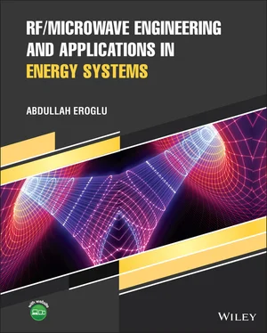
Abdullah Eroglu - RF/Microwave Engineering and Applications in Energy Systems
Здесь есть возможность читать онлайн «Abdullah Eroglu - RF/Microwave Engineering and Applications in Energy Systems» — ознакомительный отрывок электронной книги совершенно бесплатно, а после прочтения отрывка купить полную версию. В некоторых случаях можно слушать аудио, скачать через торрент в формате fb2 и присутствует краткое содержание. Жанр: unrecognised, на английском языке. Описание произведения, (предисловие) а так же отзывы посетителей доступны на портале библиотеки ЛибКат.
- Название:RF/Microwave Engineering and Applications in Energy Systems
- Автор:
- Жанр:
- Год:неизвестен
- ISBN:нет данных
- Рейтинг книги:5 / 5. Голосов: 1
-
Избранное:Добавить в избранное
- Отзывы:
-
Ваша оценка:
- 100
- 1
- 2
- 3
- 4
- 5
RF/Microwave Engineering and Applications in Energy Systems: краткое содержание, описание и аннотация
Предлагаем к чтению аннотацию, описание, краткое содержание или предисловие (зависит от того, что написал сам автор книги «RF/Microwave Engineering and Applications in Energy Systems»). Если вы не нашли необходимую информацию о книге — напишите в комментариях, мы постараемся отыскать её.
An essential text with a unique focus on RF and microwave engineering theory and its applications RF/Microwave Engineering and Applications in Energy Systems,
RF/Microwave Engineering and Applications in Energy Systems
RF/Microwave Engineering and Applications in Energy Systems — читать онлайн ознакомительный отрывок
Ниже представлен текст книги, разбитый по страницам. Система сохранения места последней прочитанной страницы, позволяет с удобством читать онлайн бесплатно книгу «RF/Microwave Engineering and Applications in Energy Systems», без необходимости каждый раз заново искать на чём Вы остановились. Поставьте закладку, и сможете в любой момент перейти на страницу, на которой закончили чтение.
Интервал:
Закладка:
5 Chapter 5Figure 5.1 Implementation of matching network between t ‐line and load.Figure 5.2 Eight possible L matching network sections.Figure 5.3 Generic L matching network sections to represent eight L sections...Figure 5.4 ZY Smith chart as a graphical tool for impedance matching.Figure 5.5 Smith chart solution for Example 5.2.Figure 5.6 Smith chart solution for Example 5.3.Figure 5.7 Input impedance using quarter‐wave transformer.Figure 5.8 Illustration of Example 5.4.Figure 5.9 Single stub matching: (a) parallel; (b) series.Figure 5.10 Illustration of double stub tuner circuit.Figure 5.11 Smith chart solution for double tuner for Example 5.5.Figure 5.12 Matching network between load and transmission line.Figure 5.13 Generic two L matching networks between source and load impedanc...Figure 5.14 Number of possible L matching networks to match source and load ...Figure 5.15 Possible L matching networks to match source and load impedance....Figure 5.16 Node quality factor illustration.Figure 5.17 Q ‐factor Smith chart.Figure 5.18 Two possible L ‐type matching networks.Figure 5.19 Smith chart solution for Example 5.7.Figure 5.20 General topologies for (a) T network and (b) PI network.Figure 5.21 Dimensions of single stub tuner.Figure 5.22 Ansoft simulation of single sub tuner.Figure 5.23 TRL calculator for electrical length in Ansoft Simulator.Figure 5.24 Single stub tuner prototype.Figure 5.25 Prototype sections: (a) load; (b) shorted stub.Figure 5.26 Measured S11 for the prototype.Figure 5.27 Illustration of the measured tuning frequency.Figure 5.28 Illustration of the matching network for Design Example 5.2.Figure 5.29 Representation of microstrip line.Figure 5.30 The simulated matching network with open stub.Figure 5.31 ADS simulation results with open stub.Figure 5.32 The simulated matching network with short stub.Figure 5.33 ADS simulation results with short stub.Figure 5.34 Microstrip line implementation with open stub.Figure 5.35 ADS simulation results of microstrip line implementation with op...Figure 5.36 Microstrip line implementation with short stub.Figure 5.37 ADS simulation results of microstrip line implementation with sh...Figure 5.38 The layout to be used for EM simulation.Figure 5.39 Microstrip layout for open stub matching network.Figure 5.40 Microstrip layout for short stub matching network.Figure 5.41 EM simulation results of the matching network.Figure 5.42 Co‐simulation circuit for open stub.Figure 5.43 Co‐simulation circuit for short stub.Figure 5.44 Simulation results for the final layout for co‐simulated open st...Figure 5.45 Simulation results for the final layout for co‐simulated short s...Figure 5.46 Problem 5.6.Figure 5.47 Problem 5.7.Figure 5.48 Problem 5.8.Figure 5.49 Problem 5.9.Figure 5.50 Amplifier impedance transformer design.Figure 5.51 Design Challenge 5.1.
6 Chapter 6Figure 6.1 Ideal resonant network response.Figure 6.2 Parallel resonant circuit.Figure 6.3 Parallel resonant network response for an underdamped case.Figure 6.4 Parallel resonant network response for an overdamped case.Figure 6.5 Parallel resonant circuit with a source current.Figure 6.6 Pole‐zero diagram for complex conjugate roots.Figure 6.7 Parallel resonant circuit transfer function characteristics.Figure 6.8 Attenuation profile.Figure 6.9 (a) Series resonant network. (b) Series resonant network response...Figure 6.10 Series resonant network with source voltage.Figure 6.11 Series resonant circuit transfer function characteristics.Figure 6.12 High frequency representation of (a) inductor and (b) capacitor....Figure 6.13 Equivalent series circuit.Figure 6.14 Equivalent parallel circuit.Figure 6.15 LC resonant network with ideal components and source.Figure 6.16 The frequency characteristics of an LC network with source.Figure 6.17 Addition of loss to parallel LC network.Figure 6.18 Attenuation profile of an LC network with loss resistor.Figure 6.19 Quality factor of an LC network with a loss resistor.Figure 6.20 Quality factor of an LC network for different source resistance ...Figure 6.21 Attenuation profile of an LC network for different source resist...Figure 6.22 Loaded LC resonant circuit.Figure 6.23 Equivalent loaded LC resonant circuit at resonance.Figure 6.24 RC series to parallel RC network transformation.Figure 6.25 Series to parallel conversion.Figure 6.26 Attenuation profile for parallel resonant network.Figure 6.27 LC series to parallel RL network transformation.Figure 6.28 LC parallel network using L with series loss transformation.Figure 6.29 LC parallel network using C with series loss transformation.Figure 6.30 Inductively coupled resonators.Figure 6.31 Inductively coupled resonators (a) below resonance and (b) above...Figure 6.32 Capacitively coupled resonators.Figure 6.33 Inductively coupled resonators (a) below resonance and (b) above...Figure 6.34 Inductively coupled resonators.Figure 6.35 Capacitively coupled resonators.Figure 6.36 (a) Attenuation profile for capacitively coupled resonators. (b)...Figure 6.37 LC impedance transformer for inductive load.Figure 6.38 LC impedance transformer for capacitive load.Figure 6.39 Amplifier output load line circuit.Figure 6.40 Capacitive voltage divider.Figure 6.41 Capacitive voltage divider with load resistor.Figure 6.42 Capacitive voltage divider with parallel to series transformatio...Figure 6.43 Tapped equivalent circuit.Figure 6.44 Equivalent tapped‐ C circuit representation using transformer.Figure 6.45 Parallel resonant circuit with tapped‐ C approach.Figure 6.46 Tapped C and L implementation for amplifiers.Figure 6.47 Attenuation profile for Example 6.5.Figure 6.48 Tapped‐ L impedance transformer.Figure 6.49 Tapped‐ L impedance transformer with parallel to series transform...Figure 6.50 Tapped‐ L equivalent circuit.Figure 6.51 Input network transformation for tapped C transformer.Figure 6.52 Output network transformation for tapped L transformer.Figure 6.53 MATLAB GUI to design tapped C and tapped L impedance transformer...Figure 6.54 Capacitively coupled amplifier circuit.Figure 6.55 Problem 6.3.Figure 6.56 Problem 6.4.Figure 6.57 Problem 6.5.Figure 6.58 Problem 6.6.Figure 6.59 Problem 6.7.Figure 6.60 Problem 6.8.Figure 6.61 Problem 6.9.Figure 6.62 Problem 6.10.
7 Chapter 7Figure 7.1 Directional coupler as a four‐port device.Figure 7.2 Symmetrical two‐line microstrip directional coupler.Figure 7.3 Coupled lines mode representation: (a) even mode; (b) odd mode.Figure 7.4 Three‐line symmetrical microstrip coupler.Figure 7.5 Generation of three‐line coupler from the design parameters of a ...Figure 7.6 Removal of the main line in a three‐line coupler for formulation ...Figure 7.7 MATLAB GUI for a two‐line microstrip directional coupler.Figure 7.8 Simulated microstrip two‐line directional coupler.Figure 7.9 Simulated results for the coupling level for a two‐line symmetric...Figure 7.10 Two‐line multilayer directional coupler.Figure 7.11 Three‐line multilayer directional coupler.Figure 7.12 Four‐port transformer directional coupler.Figure 7.13 Four‐port transformer directional coupler for circuit analysis....Figure 7.14 Six‐port transformer directional coupler.Figure 7.15 Forward mode analysis of six‐port coupler when V 2= V 3= V 4= V 5Figure 7.16 Reverse mode analysis of six‐port coupler when V 1= V 3= V 4= V 5Figure 7.17 Multistate reflectometer based on four‐port coupler and attenuat...Figure 7.18 Illustration of imperfect power circle for complex reflection co...Figure 7.19 Illustration of near intersection power circle for complex refle...Figure 7.20 n + 1 port power combiner.Figure 7.21 n + 1 power divider.Figure 7.22 Equivalent Wilkinson power divider circuit [28].Figure 7.23 Quarter wave transmission line connection in the combiner circui...Figure 7.24 N ‐way Wilkinson power divider circuit.Figure 7.25 Four‐port network for an N ‐way power divider.Figure 7.26 Even‐mode network for an N ‐way divider.Figure 7.27 Odd‐mode network for an N ‐way divider.Figure 7.28 Simplified even‐mode network for an N ‐way divider.Figure 7.29 Simplified odd‐mode network for an N ‐way divider.Figure 7.30 Isolation response versus electrical length for an N ‐way divider...Figure 7.31 VSWR response versus electrical length for an N ‐way divider.Figure 7.32 Insertion loss response versus electrical length for an N ‐way di...Figure 7.33 N ‐way Wilkinson power divider circuit with different source impe...Figure 7.34 Four‐port network for an N ‐way power divider with different sour...Figure 7.35 Even‐mode network for an N ‐way divider with different source imp...Figure 7.36 Odd‐mode network for an N ‐way divider with different source impe...Figure 7.37 Isolation response versus electrical length for an N ‐way divider...Figure 7.38 Isolation response versus electrical length for an N ‐way divider...Figure 7.39 Input VSWR response versus electrical length for an N ‐way divide...Figure 7.40 Input VSWR response versus electrical length for an N ‐way divide...Figure 7.41 Output VSWR response versus electrical length for an N ‐way divid...Figure 7.42 Output VSWR response versus electrical length for an N ‐way divid...Figure 7.43 Insertion loss response versus electrical length for an N ‐way di...Figure 7.44 Insertion loss response versus electrical length for an N ‐way di...Figure 7.45 Simulated eight‐way balanced divider.Figure 7.46 Isolation versus frequency for an eight‐way divider when θ ...Figure 7.47 Isolation versus frequency for an eight‐way divider when θ ...Figure 7.48 Insertion Loss versus frequency for an eight‐way divider when θ ...Figure 7.49 Insertion Loss versus frequency for an eight‐way divider when θ ...Figure 7.50 The input and output VSWR versus frequency when for θ = 90°...Figure 7.51 The input and output VSWR versus frequency when for θ = 70°...Figure 7.52 Simulated eight‐way unbalanced divider.Figure 7.53 Isolation versus frequency for eight‐way unbalanced divider when...Figure 7.54 Isolation versus frequency for eight‐way unbalanced divider when...Figure 7.55 Insertion loss versus frequency for eight‐way unbalanced divider...Figure 7.56 Insertion loss versus frequency for eight‐way unbalanced divider...Figure 7.57 The input and output VSWR versus frequency when for θ = 90°...Figure 7.58 The input and output VSWR versus frequency when for θ = 70°...Figure 7.59 MATLAB GUI output for an eight‐way balanced divider when θ ...Figure 7.60 MATLAB GUI output for an eight‐way unbalanced divider when θ ...Figure 7.61 N ‐way combiner circuit.Figure 7.62 Distributed to lumped conversion.Figure 7.63 Transformation from (a) a π network to (b) an L network.Figure 7.64 (a) Two‐line microstrip coupler design for 15 dB coupling using ...Figure 7.65 Simulation results of a two‐line microstrip coupler at 300 MHz f...Figure 7.66 Three‐line microstrip coupler with 2D view.Figure 7.67 Simulation results of a three‐line microstrip coupler at 300 MHz...Figure 7.68 The prototype of a three‐line directional coupler using TMM10 ma...Figure 7.69 Measurement results for three‐line coupler at 300 MHz for coupli...Figure 7.70 MATLAB GUI for transformer coupler design.Figure 7.71 Frequency domain circuit simulator using S parameters.Figure 7.72 Simulated coupling level for a transformer coupler in frequency ...Figure 7.73 Simulated isolation level for a transformer coupler in frequency...Figure 7.74 Simulated directivity level for a transformer coupler in frequen...Figure 7.75 Time domain simulation for a transformer coupler.Figure 7.76 Simulated coupling and isolation levels for a transformer couple...Figure 7.77 Simulated directivity level for a transformer coupler in time do...Figure 7.78 Macros used in PSpice for coupling, isolation, and directivity s...Figure 7.79 Constructed transformer coupler for 27.12 MHz operation.Figure 7.80 Semirigid coax cable used in transformer coupler.Figure 7.81 Measured coupling of a constructed transformer coupler.Figure 7.82 Measured isolation of a constructed transformer coupler.Figure 7.83 Measured input impedance of a constructed transformer coupler.Figure 7.84 Measured isolation and coupling of a constructed transformer cou...Figure 7.85 Measured directivity of a constructed transformer coupler.Figure 7.86 MATLAB GUI output for a three‐way unbalanced combiner when θ ...Figure 7.87 Spiral inductor layout.Figure 7.88 Simplified equivalent circuit for spiral inductor without loss f...Figure 7.89 Spiral inductor model is inserted into an L network.Figure 7.90 (a) One‐port measurement network and (b) its impedance plot for ...Figure 7.91 Final form of the lumped‐element distribution circuit with spira...Figure 7.92 Simulation results for the insertion loss between each distribut...Figure 7.93 Simulation results for the isolation between each distribution p...Figure 7.94 Simulated three‐way combiner in planar form using L network topo...Figure 7.95 Simulation results for a three‐way combiner in planar form using...Figure 7.96 Current and near‐field distribution for a three‐way combiner.Figure 7.97 Co‐simulation of a three‐way combiner.Figure 7.98 Simulated planar combining circuitry for a three‐way combiner.Figure 7.99 Spiral inductor that is simulated with method‐of‐moment‐based el...Figure 7.100 Simulated spiral inductor inductance versus frequency.Figure 7.101 Simulated spiral inductor quality factor versus frequency.Figure 7.102 Input VSWR versus frequency for three‐way microstrip combiner....Figure 7.103 Three‐way combiner implemented in planar form using L network t...Figure 7.104 Measurement results for insertion loss of a three‐way combiner ...Figure 7.105 Measurement results for insertion loss of three‐way combiner in...Figure 7.106 Measured combiner port impedance versus frequency.Figure 7.107 Spiral inductor on alumina substrate.Figure 7.108 Measured inductance value of spiral inductor versus frequency....Figure 7.109 Measured insertion loss of spiral inductor versus frequency.Figure 7.110 MATLAB GUI output for a three‐way unbalanced combiner when θ ...Figure 7.111 Problem 7.4.Figure 7.112 Problem 7.7.Figure 7.113 Problem 7.9.Figure 7.114 Power divider antenna feeder system.
Читать дальшеИнтервал:
Закладка:
Похожие книги на «RF/Microwave Engineering and Applications in Energy Systems»
Представляем Вашему вниманию похожие книги на «RF/Microwave Engineering and Applications in Energy Systems» списком для выбора. Мы отобрали схожую по названию и смыслу литературу в надежде предоставить читателям больше вариантов отыскать новые, интересные, ещё непрочитанные произведения.
Обсуждение, отзывы о книге «RF/Microwave Engineering and Applications in Energy Systems» и просто собственные мнения читателей. Оставьте ваши комментарии, напишите, что Вы думаете о произведении, его смысле или главных героях. Укажите что конкретно понравилось, а что нет, и почему Вы так считаете.
