X-Ray Fluorescence in Biological Sciences
Здесь есть возможность читать онлайн «X-Ray Fluorescence in Biological Sciences» — ознакомительный отрывок электронной книги совершенно бесплатно, а после прочтения отрывка купить полную версию. В некоторых случаях можно слушать аудио, скачать через торрент в формате fb2 и присутствует краткое содержание. Жанр: unrecognised, на английском языке. Описание произведения, (предисловие) а так же отзывы посетителей доступны на портале библиотеки ЛибКат.

- Название:X-Ray Fluorescence in Biological Sciences
- Автор:
- Жанр:
- Год:неизвестен
- ISBN:нет данных
- Рейтинг книги:5 / 5. Голосов: 1
-
Избранное:Добавить в избранное
- Отзывы:
-
Ваша оценка:
X-Ray Fluorescence in Biological Sciences: краткое содержание, описание и аннотация
Предлагаем к чтению аннотацию, описание, краткое содержание или предисловие (зависит от того, что написал сам автор книги «X-Ray Fluorescence in Biological Sciences»). Если вы не нашли необходимую информацию о книге — напишите в комментариях, мы постараемся отыскать её.
Discover a comprehensive exploration of X-ray fluorescence in chemical biology and the clinical and plant sciences X-Ray Fluorescence in Biological Sciences: Principles, Instrumentation, and Applications
X-Ray Fluorescence in Biological Sciences: Principles, Instrumentation, and Applications
X-Ray Fluorescence in Biological Sciences — читать онлайн ознакомительный отрывок
Ниже представлен текст книги, разбитый по страницам. Система сохранения места последней прочитанной страницы, позволяет с удобством читать онлайн бесплатно книгу «X-Ray Fluorescence in Biological Sciences», без необходимости каждый раз заново искать на чём Вы остановились. Поставьте закладку, и сможете в любой момент перейти на страницу, на которой закончили чтение.
Интервал:
Закладка:
1 In TXRF, the primary beam falls on the sample/support at an angle less than the critical angle which is <1° for almost all materials and depends on the energy of the X‐ray beam as well as density and atomic number (Z) of the reflector materials. This feature of TXRF ensures that the incident X‐rays do not penetrate deep into the sample supports and hence the scattered background is drastically reduced and leads to far better detection limits compared to conventional XRF.
2 As the primary parallel incident X‐ray beam falls on the sample support at an angle less than the critical angle, the sample support has to be a flat polished surface so that a fixed angle below the critical angle of support can be maintained for the impinging beam to totally reflect from it. In this situation, if a thin film of the sample having thickness of a few nanometers is deposited on the intersection area of the incident and reflected beams, it will be excited by the incident as well as by the totally reflected beams from the support. This arrangement results in almost double excitation of the sample compared to that in EDXRF and thus, increases the intensity of fluorescent X‐rays compared to that in EDXRF by about two times.
3 Since the glancing as well as the reflection angles are generally below one degree (very near to zero degree) the detector can be brought very close to the sample deposited on the support ensuring the angle between the incident X‐ray beam and the detector to be about 90°. This arrangement leads to 0–90° geometry of beam and detector, required for attaining a low background in XRF (here in TXRF).
The above geometrical arrangement takes care of the problems, associated with EDXRF, which are responsible for higher (inferior) detection limits and provides excellent elemental detection limits in TXRF comparable with other trace determination techniques, e.g. ICP‐OES, ICP‐MS, etc. In addition, the sample thickness is very small (a few nm) and hence the matrix effects associated are also negligible [8–10].
4.4.2 Theoretical Considerations
X‐rays are electromagnetic radiation and follow the law of refraction in a similar manner as any other electromagnetic radiation when traveling from one medium (e.g. air) to another (e.g. glass) as shown in Figure 4.1. The refraction of the X‐rays is governed by the formula:
(4.1) 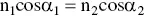
In Eq. (4.1), n 1and α 1are the refractive index and the glancing angle of the incident X‐rays in medium 1, respectively, whereas n 2and α 2are these values for medium 2.
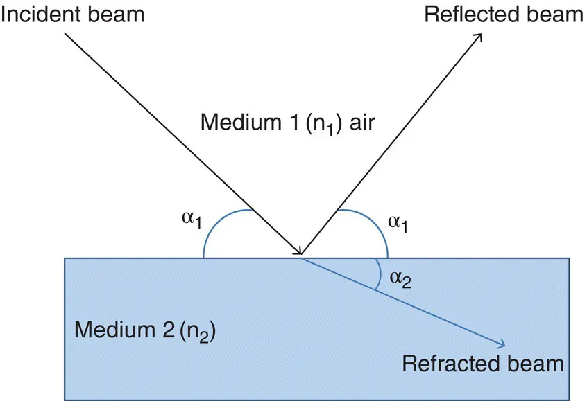
Figure 4.1 X‐rays undergoing reflection and refraction.
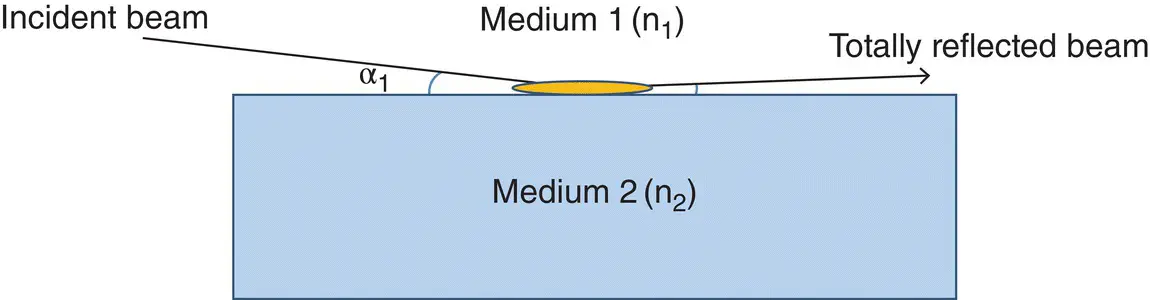
Figure 4.2 Depiction of total reflection of X‐rays on the sample support containing sample ( yellow colour).
For X‐rays, any medium is rarer than air or vacuum and hence, n 1(air) > n 2(medium). This means that when X‐rays pass from a denser medium (e.g. air) to a rarer medium (e.g. glass) then, cosα 2> cos α 1thereby α 2< α 1. So, if the glancing angle α 1is reduced continuously, at one value of α 1, α 2shall be zero and the refracted beam shall be just touching the supports surface and passing over it. Since the glancing angle in this situation is almost near to zero degree, the reflected beam shall also pass almost touching over the surface after reflection.This situation is depicted in the Figure 4.2and is known as the condition of total reflection; the glancing angle at this stage is called the critical angle. The critical angle is very crucial in TXRF analysis as total reflection of X‐rays happen when the glancing angle of the X‐ray beam is equal to or less than the critical angle. The critical angle ( α crit) can be expressed by the following Eq. (4.2):
(4.2) 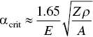
where, E is the energy of incident X‐ray beam (in keV) undergoing total reflection, ρ is the density in g/cm 3of the second medium, and Z and A are the atomic number and atomic mass of the second medium, respectively. The above formula holds true only for the X‐ray energies above the absorption edges of the medium [8–10].
It is clear from the above elaboration that for a glancing angle lower than the critical angle, there will be no refraction and the X‐ray beam falling on the sample is totally reflected from the second medium back to first medium. This means that the penetration of X‐rays in the medium, when the glancing angle is below the critical angle, is negligible and this is very advantageous for TXRF analysis. Thus, three physical quantities: critical angle, reflectivity, and penetration depth, are important parameters for TXRF analysis. The critical angle is already discussed in detail above.
The reflectivity of a medium is defined as the ratio of the intensity of the reflected beam and that of the incident beam. In TXRF analysis, a reflectivity of about 100% is desirable. For X‐rays falling on a medium at an angle greater than that of critical angle, reflectivity is low but it increases drastically at the critical angle and reaches almost 100% when the angle of incident is slightly lower than the critical angle. Penetration depth, which is defined as that depth of a homogeneous medium that a beam can penetrate, and its intensity is reduced to 1/e, or 37% of its initial value. As mentioned above the penetration depth in TXRF geometry is very small (only a few nanometers). Both these factors, high reflectivity and low penetration depth avoid the interaction of X‐rays with the medium and hence, the scattering. Therefore, spectral background is very low in TXRF.
Table 4.1 Some sample support materials suitable for use in TXRF analysis and their characteristics for TXRF analysis. Data from Klockenkämper [10].
| Support material | Critical angle for Mo Kα (17.44 keV) (Degrees) | Reflectivity for Mo Kα (17.44 keV) at critical angle | Critical angle for WLα (8.39 keV) (Degrees) | Reflectivity for W Lα (8.39 keV) at critical angle |
|---|---|---|---|---|
| Plexiglas | 0.08 | 0.932 | 0.16 | 0.879 |
| Glassy Carbon | 0.08 | 0.939 | 0.17 | 0.884 |
| Boron Carbide | 0.10 | 0.93 | 0.21 | 0.876 |
| Quartz | 0.10 | 0.855 | 0.21 | 0.734 |
| Platinum | 0.28 | 0.394 | 0.58 | 0.453 |
| Gold | 0.26 | 0.387 | 0.55 | 0.448 |
The critical angle given in the above equation depends on the energy of the X‐ray beam and on the material being used as a reflector. It is a very small value in the range of 0–1°. The critical angles and reflectivities at critical angles for some materials with respect to different X‐ray sources, e.g. Mo Kα and W Kα X‐rays have been given in Table 4.1[10]. Since the critical angle is so small, it is imperative that the X‐rays used for sample excitation travel parallel to each other in the X‐ray beam and do not have any diversion. Special type of line focus X‐ray tubes are used for this purpose. Moreover, sufficient smoothness and flatness of the supports are essential to maintain such a small angle. Different types of sample supports are used in TXRF analysis. The sample supports to be used for TXRF analysis should be flat, highly reflecting, and made from pure and chemically inert material. In addition, they should be either of a low Z material, e.g. quartz, Plexiglass or a pure single element metal, (e.g. gold) to ensure that there are no more than a few characteristic X‐ray lines from the support material and hence, interference with the analyte lines from the sample are kept to a minimum. Further, the supports should be reusable and easy to clean so that TXRF analysis is simple and economical.
Читать дальшеИнтервал:
Закладка:
Похожие книги на «X-Ray Fluorescence in Biological Sciences»
Представляем Вашему вниманию похожие книги на «X-Ray Fluorescence in Biological Sciences» списком для выбора. Мы отобрали схожую по названию и смыслу литературу в надежде предоставить читателям больше вариантов отыскать новые, интересные, ещё непрочитанные произведения.


Обсуждение, отзывы о книге «X-Ray Fluorescence in Biological Sciences» и просто собственные мнения читателей. Оставьте ваши комментарии, напишите, что Вы думаете о произведении, его смысле или главных героях. Укажите что конкретно понравилось, а что нет, и почему Вы так считаете.