Stephen W. S. McKeever - A Course in Luminescence Measurements and Analyses for Radiation Dosimetry
Здесь есть возможность читать онлайн «Stephen W. S. McKeever - A Course in Luminescence Measurements and Analyses for Radiation Dosimetry» — ознакомительный отрывок электронной книги совершенно бесплатно, а после прочтения отрывка купить полную версию. В некоторых случаях можно слушать аудио, скачать через торрент в формате fb2 и присутствует краткое содержание. Жанр: unrecognised, на английском языке. Описание произведения, (предисловие) а так же отзывы посетителей доступны на портале библиотеки ЛибКат.
- Название:A Course in Luminescence Measurements and Analyses for Radiation Dosimetry
- Автор:
- Жанр:
- Год:неизвестен
- ISBN:нет данных
- Рейтинг книги:4 / 5. Голосов: 1
-
Избранное:Добавить в избранное
- Отзывы:
-
Ваша оценка:
A Course in Luminescence Measurements and Analyses for Radiation Dosimetry: краткое содержание, описание и аннотация
Предлагаем к чтению аннотацию, описание, краткое содержание или предисловие (зависит от того, что написал сам автор книги «A Course in Luminescence Measurements and Analyses for Radiation Dosimetry»). Если вы не нашли необходимую информацию о книге — напишите в комментариях, мы постараемся отыскать её.
A Course in Luminescence Measurements and Analyses for Radiation Dosimetry — читать онлайн ознакомительный отрывок
Ниже представлен текст книги, разбитый по страницам. Система сохранения места последней прочитанной страницы, позволяет с удобством читать онлайн бесплатно книгу «A Course in Luminescence Measurements and Analyses for Radiation Dosimetry», без необходимости каждый раз заново искать на чём Вы остановились. Поставьте закладку, и сможете в любой момент перейти на страницу, на которой закончили чтение.
Интервал:
Закладка:
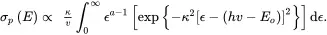
For deep traps, Lucovsky (1964) approximated the potential in the region of the defect to a delta function and assumed a plane wave excited-state wavefunction to derive:
 (2.16)
The cross-section reaches a maximum at hv=2Eo, and the coulombic field is taken into account.
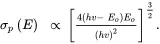
A further assumption in the derivation of Equation ( 2.16) is that the effective mass me* of the electron in the conduction band can be used also for the electron in the localized state. By using the electron rest mass mo instead of me* while the electron is localized, Grimmeis and Ledebo (1975a, 1975b) derived:
 (2.17)
also using a plane-wave final state and the assumption of parabolic bands.
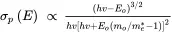
By taking into account strong phonon coupling between the lattice and the trapped electron, Noras (1980) (see also Chruścińska 2010) derived:
 (2.18)
The parameter ϵ is a dummy variable having the dimensions of energy, and a = 5/2 or 3/2 for forbidden and allowed transitions, respectively. The parameter κ is given by:
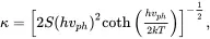 (2.19)
where again S is the Huang-Rhys factor and hvph is the energy of the phonon vibrational mode.
For a purely electronic transition (no phonon coupling):
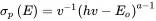 (2.20)
for hv>>Eo, and σp(E)=0 for hvEquation 2.20with Equations 2.16and 2.17.
Several other expressions for σp(E) also exist (Jaros 1977; Blakemore and Rahimi 1984; Ridley 1988; Böer 1990; Landsberg 2003).
OSL signals from dosimetry materials originate from the release of electrons from deep trapping states and thus the expressions most frequently used to represent the photoionization cross-section of such centers are Equations 2.16, 2.17, and 2.18. A comparison of the shapes of some of these expressions is given in Figure 2.9.
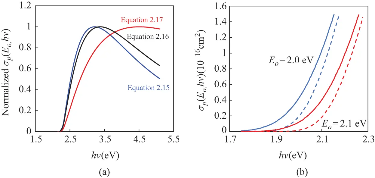
Figure 2.009 (a) Examples of postulated photoionization cross-sections as a function of stimulation energy. In this depiction, all curves are normalized to their maximum value and the optical trap depth is Eo = 2.25 eV. (b) Example photoionization cross-sections when phonon coupling is allowed. In this figure, the Huang-Rhys factor S is 10 and the temperature is 300 K. Curves corresponding to two values for Eo are illustrated, each with two curve shapes corresponding to values of hvph of 20 meV (dashed lines) and 40 meV (full lines). (Adapted from Chrus´cin´ska 2010.)
Exercise 2.2
From the literature, look up as many expressions as you can find for the photoionization cross-section σp(E). Plot each and compare shapes. Discuss and explain the differences, assumptions, limitations, etc.
2.2.2 Trapping and Recombination Processes
Once an electron-hole pair has been generated by radiation, trapping and recombination processes remove the free charge carriers (electrons in the conduction band and holes in the valence band) from their respective delocalized bands. Several mechanisms can lead to electron or hole capture and recombination. In principle, direct recombination of a free electron with a free hole (i.e. a transition directly across the gap) is possible, but is highly unlikely. Not only would a large amount of energy have to be dissipated, but conservation of momentum requires that the electron and hole recombine with oppositely directed momenta. If the direct recombination process is non-radiative, the energy would have to be dissipated via phonon vibrations. The materials used for radiation dosimetry are wide-band-gap insulators and the band gaps are several electron-volts wide. (For example, in LiF the band gap it is ~14 eV.) Considering that phonon energies in solids are about 0.03 eV at room temperature, thousands of phonons would be needed to couple with the electron in order to dissipate the energy. In contrast, if the energy was dissipated radiatively in the form of photons, the emitted photon wavelengths (using LiF as an example) would be around 80–90 nm, in contrast to the visible wavelengths observed in luminescence measurements. These considerations lead to the conclusion that recombination of charges occurs via localized states in a process known as Shockley-Read-Hall (SRH) recombination. The recombination process leaves the recombination site (defect) in an excited state, radiative relaxation of which produces the luminescence.
Considering only the recombination of free electrons with trapped holes, the rate of SRH recombination can be seen to be dependent on the free electron density, the density of trapped holes, and the temperature. The free carrier lifetime τ of an electron or a hole can be expressed as:
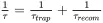 (2.21)
where τtrap and τrecom are trapping and recombination lifetimes respectively, given by:
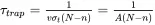 (2.22)
and
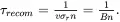 (2.23)
In these expressions v is the free carrier thermal velocity ( ve for electrons in the conduction band or vh for holes in the valence band); σ is the relative capture-cross section for either capture by (N−n) empty traps, or for recombination with n trapped charges of opposite sign (free electrons by trapped holes or free holes by trapped electrons) and N and n are the total concentrations of available traps and the concentration of filled traps, respectively. The products A=vσt and B=vσr are the respective trapping/recombination “probabilities” or “transition rates,” in units of m 3.s –1.
Capture of electrons or holes at localized states can be via multi-phonon processes, cascade capture, Auger emission or radiative recombination. (See Mott (1978) for an overview and Landsberg (2003) for more detailed treatments.) As argued above, radiative recombination can be neglected for SRH recombination at a level deep within the band gap of a wide-band-gap insulator. Auger emission, either direct or exciton-enhanced, occurs when the energy of the free carrier is transferred to another electron or hole. The process is not often considered in dosimetry materials, but is a possibility to be considered. The temperature dependence of the capture cross-section for the Auger process is usually a power law, σ∝T−a.
Читать дальшеИнтервал:
Закладка:
Похожие книги на «A Course in Luminescence Measurements and Analyses for Radiation Dosimetry»
Представляем Вашему вниманию похожие книги на «A Course in Luminescence Measurements and Analyses for Radiation Dosimetry» списком для выбора. Мы отобрали схожую по названию и смыслу литературу в надежде предоставить читателям больше вариантов отыскать новые, интересные, ещё непрочитанные произведения.


Обсуждение, отзывы о книге «A Course in Luminescence Measurements and Analyses for Radiation Dosimetry» и просто собственные мнения читателей. Оставьте ваши комментарии, напишите, что Вы думаете о произведении, его смысле или главных героях. Укажите что конкретно понравилось, а что нет, и почему Вы так считаете.