Ibrahim Dogan - Advanced PIC Microcontroller Projects in C
Здесь есть возможность читать онлайн «Ibrahim Dogan - Advanced PIC Microcontroller Projects in C» весь текст электронной книги совершенно бесплатно (целиком полную версию без сокращений). В некоторых случаях можно слушать аудио, скачать через торрент в формате fb2 и присутствует краткое содержание. Город: Burlington, Год выпуска: 2008, ISBN: 2008, Издательство: Elsevier Ltd, Жанр: Программирование, Компьютерное железо, на английском языке. Описание произведения, (предисловие) а так же отзывы посетителей доступны на портале библиотеки ЛибКат.

- Название:Advanced PIC Microcontroller Projects in C
- Автор:
- Издательство:Elsevier Ltd
- Жанр:
- Год:2008
- Город:Burlington
- ISBN:978-0-7506-8611-2
- Рейтинг книги:5 / 5. Голосов: 1
-
Избранное:Добавить в избранное
- Отзывы:
-
Ваша оценка:
Advanced PIC Microcontroller Projects in C: краткое содержание, описание и аннотация
Предлагаем к чтению аннотацию, описание, краткое содержание или предисловие (зависит от того, что написал сам автор книги «Advanced PIC Microcontroller Projects in C»). Если вы не нашли необходимую информацию о книге — напишите в комментариях, мы постараемся отыскать её.
• Features 20 complete, tried and test projects
• Includes a CD-ROM of all the programs, hex listings, diagrams, and data sheets
Advanced PIC Microcontroller Projects in C — читать онлайн бесплатно полную книгу (весь текст) целиком
Ниже представлен текст книги, разбитый по страницам. Система сохранения места последней прочитанной страницы, позволяет с удобством читать онлайн бесплатно книгу «Advanced PIC Microcontroller Projects in C», без необходимости каждый раз заново искать на чём Вы остановились. Поставьте закладку, и сможете в любой момент перейти на страницу, на которой закончили чтение.
Интервал:
Закладка:
char CANWrite(long id, char *data, char datalen,
char CAN_TX_MSG_FLAGS)
id is the CAN message identifier. Only 11 or 29 bits may be used depending on message type (standard or extended). data is an array of bytes up to 8 where the data to be sent is stored. datalen is the length of the data (1 to 8).
CAN_TX_MSG_FLAGS can be one of the following:
• CAN_TX_PRIORITY_0 Transmit priority 0
• CAN_TX_PRIORITY_1 Transmit priority 1
• CAN_TX_PRIORITY_2 Transmit priority 2
• CAN_TX_PRIORITY_3 Transmit priority 3
• CAN_TX_STD_FRAME Standard identifier message
• CAN_TX_XTD_FRAME Extended identifier message
• CAN_TX_NO_RTR_FRAME Non RTR message
• CAN_TX_RTR_FRAME RTR message
These flags can be bitwise AND’ed if desired.
9.11 CAN Bus Programming
To operate the PIC18F258 microcontroller on the CAN bus, perform the following steps:
• Configure the CAN bus I/O port directions (RB2 and RB3)
• Initialize the CAN module ( CANInitialize )
• Set the CAN module to CONFIG mode ( CANSetOperationMode )
• Set the mask registers ( CANSetMask )
• Set the filter registers ( CANSetFilter )
• Set the CAN module to normal mode ( CANSetOperationMode )
• Write/read data ( CANWrite / CANRead )
PROJECT 9.1 — Temperature Sensor CAN Bus Project
The following is a simple two-node CAN bus–based project. The block diagram of the project is shown in Figure 9.15. The system is made up of two CAN nodes. One node (called DISPLAY node) requests the temperature every second and displays it on an LCD. This process is repeated continuously. The other node (called COLLECTOR node) reads the temperature from an external semiconductor temperature sensor.
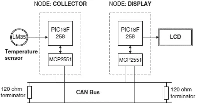
Figure 9.15: Block diagram of the project
The project’s circuit diagram is given in Figure 9.16. Two CAN nodes are connected together using a two-meter twisted pair cable, terminated with a 120-ohm resistor at each end.
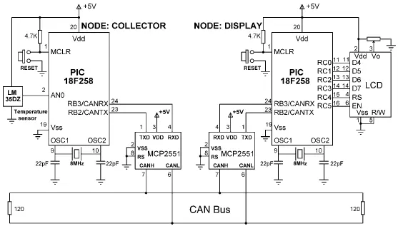
Figure 9.16: Circuit diagram of the project
The DISPLAY Processor
Like the COLLECTOR processor, the DISPLAY processor consists of a PIC18F258 microcontroller with a built-in CAN module and an MCP2551 transceiver chip. The microcontroller is operated from an 8MHz crystal. The MCLR input is connected to an external reset button. The CAN outputs (RB2/CANTX and RB3/CANRX) of the microcontroller are connected to the TXD and RXD inputs of the MCP2551. Pins CANH and CANL of the transceiver chip are connected to the CAN bus. An HD44780-type LCD is connected to PORTC of the microcontroller to display the temperature values.
The COLLECTOR Processor
The COLLECTOR processor consists of a PIC18F258 microcontroller with a built-in CAN module and an MCP2551 transceiver chip. The microcontroller is operated from an 8MHz crystal. The MCLR input is connected to an external reset button. Analog input AN0 of the microcontroller is connected to a LM35DZ-type semiconductor temperature sensor. The sensor can measure temperature in the range of 0°C to 100°C and generates an analog voltage directly proportional to the measured temperature (i.e., the output is 10mV/°C). For example, at 20°C the output voltage is 200mV.
The CAN outputs (RB2/CANTX and RB3/CANRX) of the microcontroller are connected to the TXD and RXD inputs of an MCP2551-type CAN transceiver chip. The CANH and CANL outputs of this chip are connected directly to a twisted cable terminating at the CAN bus. The MCP2551 is an 8-pin chip that supports data rates up to 1Mb/s. The chip can drive up to 112 nodes. An external resistor connected to pin 8 of the chip controls the rise and fall times of CANH and CANL so that EMI can be reduced. For high-speed operation this pin should be connected to ground. A reference voltage equal to VDD/2 is output from pin 5 of the chip.
The program listing is in two parts: the DISPLAY program and the COLLECTOR program. The operation of the system is as follows:
• The DISPLAY processor requests the current temperature from the COLLECTOR processor over the CAN bus
• The COLLECTOR processor reads the temperature, formats it, and sends to the DISPLAY processor over the CAN bus
• The DISPLAY processor reads the temperature from the CAN bus and then displays it on the LCD
• This process is repeated every second
DISPLAY Program
Figure 9.17 shows the program listing of the DISPLAY program, called DISPLAY.C. At the beginning of the program PORTC pins are configured as outputs, RB3 is configured as input (CANRX), and RB2 is configured as output (CANTX). In this project the CAN bus bit rate is selected as 100Kb/s. With a microcontroller clock frequency of 8MHz, the Baud Rate Calculator program (see Figure 9.14) is used to calculate the timing parameters as:
SJW = 1
BRP = 1
Phase_Seg1 = 6
Phase_Seg2 = 7
Prop_Seg = 6
/**********************************************************************
CAN BUS EXAMPLE - NODE: DISPLAY
===============================
This is the DISPLAY node of the CAN bus example. In this project a PIC18F258
type microcontroller is used. An MCP2551 type CAN bus transceiver is used to
connect the microcontroller to the CAN bus. The microcontroller is operated
from an 8MHz crystal with an external reset button.
Pin CANRX and CANTX of the microcontroller are connected to pins RXD
and TXD of the transceiver chip respectively. Pins CANH and CANL of
the transceiver chip are connected to the CAN bus.
An LCD is connected to PORTC of the microcontroller. The ambient
temperature is read from another CAN node and is displayed on the LCD.
The LCD is connected to the microcontroller as follows:
Microcontroller LCD
RC0 D4
RC1 D5
RC2 D6
RC3 D7
RC4 RS
RC5 EN
CAN speed parameters are:
Microcontroller clock: 8MHz
CAN Bus bit rate: 100Kb/s
Sync_Seg: 1
Prop_Seg: 6
Phase_Seg1: 6
Phase_Seg2: 7
SJW: 1
BRP: 1
Sample point: 65%
Author: Dogan Ibrahim
Date: October 2007
File: DISPLAY.C
**********************************************************************/
void main() {
unsigned char temperature, data[8];
unsigned short init_flag, send_flag, dt, len, read_flag;
char SJW, BRP, Phase_Seg1, Phase_Seg2, Prop_Seg, txt[4];
long id, mask;
TRISC = 0; // PORTC are outputs (LCD)
TRISB = 0x08; // RB2 is output, RB3 is input
//
// CAN BUS Parameters
//
SJW = 1;
BRP = 1;
Phase_Seg1 = 6;
Phase_Seg2 = 7;
Интервал:
Закладка:
Похожие книги на «Advanced PIC Microcontroller Projects in C»
Представляем Вашему вниманию похожие книги на «Advanced PIC Microcontroller Projects in C» списком для выбора. Мы отобрали схожую по названию и смыслу литературу в надежде предоставить читателям больше вариантов отыскать новые, интересные, ещё непрочитанные произведения.


Обсуждение, отзывы о книге «Advanced PIC Microcontroller Projects in C» и просто собственные мнения читателей. Оставьте ваши комментарии, напишите, что Вы думаете о произведении, его смысле или главных героях. Укажите что конкретно понравилось, а что нет, и почему Вы так считаете.