Ibrahim Dogan - Advanced PIC Microcontroller Projects in C
Здесь есть возможность читать онлайн «Ibrahim Dogan - Advanced PIC Microcontroller Projects in C» весь текст электронной книги совершенно бесплатно (целиком полную версию без сокращений). В некоторых случаях можно слушать аудио, скачать через торрент в формате fb2 и присутствует краткое содержание. Город: Burlington, Год выпуска: 2008, ISBN: 2008, Издательство: Elsevier Ltd, Жанр: Программирование, Компьютерное железо, на английском языке. Описание произведения, (предисловие) а так же отзывы посетителей доступны на портале библиотеки ЛибКат.

- Название:Advanced PIC Microcontroller Projects in C
- Автор:
- Издательство:Elsevier Ltd
- Жанр:
- Год:2008
- Город:Burlington
- ISBN:978-0-7506-8611-2
- Рейтинг книги:5 / 5. Голосов: 1
-
Избранное:Добавить в избранное
- Отзывы:
-
Ваша оценка:
Advanced PIC Microcontroller Projects in C: краткое содержание, описание и аннотация
Предлагаем к чтению аннотацию, описание, краткое содержание или предисловие (зависит от того, что написал сам автор книги «Advanced PIC Microcontroller Projects in C»). Если вы не нашли необходимую информацию о книге — напишите в комментариях, мы постараемся отыскать её.
• Features 20 complete, tried and test projects
• Includes a CD-ROM of all the programs, hex listings, diagrams, and data sheets
Advanced PIC Microcontroller Projects in C — читать онлайн бесплатно полную книгу (весь текст) целиком
Ниже представлен текст книги, разбитый по страницам. Система сохранения места последней прочитанной страницы, позволяет с удобством читать онлайн бесплатно книгу «Advanced PIC Microcontroller Projects in C», без необходимости каждый раз заново искать на чём Вы остановились. Поставьте закладку, и сможете в любой момент перейти на страницу, на которой закончили чтение.
Интервал:
Закладка:
• Synchronization segment (Sync_Seg)
• Propagation time segment (Prop_Seg)
• Phase buffer segment 1 (Phase_Seg1)
• Phase buffer segment 2 (Phase_Seg2)
The Sync_Seg segment is used to synchronize various nodes on the bus, and an edge is expected to lie within this segment. The Prop_Seg segment compensates for physical delay times within the network. The Phase_Seg1 and Phase_Seg2 segments compensate for edge phase errors. These segments can be lengthened or shortened by synchronization. The sample point is the point in time where the actual bit value is located and occurs at the end of Phase_Seg1 . A CAN controller can be configured to sample three times and use a majority function to determine the actual bit value.
Each segment is divided into units known as time quantum, or T Q. A desired bit timing can be set by adjusting the number of T Q’s that comprise one message bit and the number of T Q’s that comprise each segment in it. The T Qis a fixed unit derived from the oscillator period, and the time quantum of each segment can vary from 1 to 8. The lengths of the various time segments are:
• Sync_Seg is 1 time quantum long
• Prop_Seg is programmable as 1 to 8 time quanta long
• Phase_Seg1 is programmable as 1 to 8 time quanta long
• Phase_Seg2 is programmable as 2 to 8 time quanta long
By setting the bit timing, a sampling point can be set so multiple units on the bus can sample messages with the same timing.
The nominal bit time is programmable from a minimum of 8 time quanta to a maximum of 25 time quanta. By definition, the minimum nominal bit time is 1μs, corresponding to a maximum 1Mb/s rate. The nominal bit time (T BIT) is given by:
T BIT = T Q * (Sync_Seg + Prop_Seg + Phase_Seg1 + Phase_Seg2) (9.1)
and the nominal bit rate (NBR) is
NBR = 1/T BIT (9.2)
The time quantum is derived from the oscillator frequency and the programmable baud rate prescaler, with integer values from 1 to 64. The time quantum can be expressed as:
T Q = 2 * (BRP + 1)=F OSC (9.3)
where T Qis in μs, F OSCis in MHz, and BRP is the baud rate prescaler (0 to 63).
Equation (9.2) can be written as
T Q = 2 * (BRP + 1) * T OSC (9.4)
where T OSCis in μs.
An example of the calculation of a nominal bit rate follows.
Assuming a clock frequency of 20MHz, a baud rate prescaler value of 1, and a nominal bit time of T BIT=8*T Q, determine the nominal bit rate.
Using equation (9.3),
T Q = 2 * (1 + 1)/20 = 0.2μs
also
T BIT = 8 * T Q = 8 * 0.2 = 1.6μs
From Equation (9.2),
NBR = 1/T BIT = 1/1.6μs = 625.000bites/s or 625Kb/s
In order to compensate for phase shifts between the oscillator frequencies of nodes on a bus, each CAN controller must synchronize to the relevant signal edge of the received signal. Two types of synchronization are defined: hard synchronization and resynchronization. Hard synchronization is used only at the beginning of a message frame, when each CAN node aligns the Sync_Seg of its current bit time to the recessive or dominant edge of the transmitted start of frame. According to the rules of synchronization, if a hard synchronization occurs, there will not be a resynchronization within that bit time.
With resynchronization, Phase_Seg1 may be lengthened or Phase_Seg2 may be shortened. The amount of change in the phase buffer segments has an upper bound given by the synchronization jump width (SJW). The SJW is programmable between 1 and 4, and its value is added to Phase_Seg1 or subtracted from Phase_Seg2 .
9.8 PIC Microcontroller CAN Interface
In general, any type of PIC microcontroller can be used in CAN bus–based projects, but some PIC microcontrollers (e.g., PIC18F258) have built-in CAN modules, which can simplify the design of CAN bus–based systems. Microcontrollers with no built-in CAN modules can also be used in CAN bus applications, but additional hardware and software are required, making the design costly and also more complex.
Figure 9.11 shows the block diagram of a PIC microcontroller–based CAN bus application, using a PIC16 or PIC12-type microcontroller (e.g., PIC16F84) with no built-in CAN module. The microcontroller is connected to the CAN bus using an external MCP2515 CAN controller chip and an MCP2551 CAN bus transceiver chip. This configuration is suitable for a quick upgrade to an existing design using any PIC microcontroller.
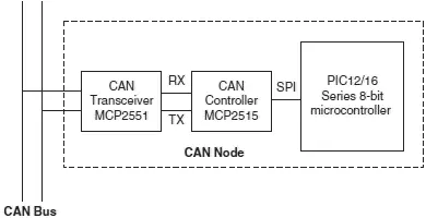
Figure 9.11: CAN node with any PIC microcontroller
For new CAN bus–based designs it is easier to use a PIC microcontroller with a built-in CAN module. As shown in Figure 9.12, such devices include built-in CAN controller hardware on the chip. All that is required to make a CAN node is to add a CAN transceiver chip. Table 9.2 lists some of the PIC microcontrollers that include a CAN module.
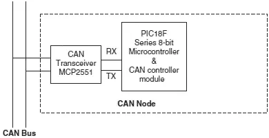
Figure 9.12: CAN node with integrated CAN module
Table 9.2: Some popular PIC microcontrollers that include CAN modules
| Device | Pins | Flash (KB) | SRAM (KB) | EEPROM (bytes) | A/D | CAN module | SPI | UART |
|---|---|---|---|---|---|---|---|---|
| 18F258 | 28 | 16 | 768 | 256 | 5 | 1 | 1 | 1 |
| 18F2580 | 28 | 32 | 1536 | 256 | 8 | 1 | 1 | 1 |
| 18F2680 | 28 | 64 | 3328 | 1024 | 8 | 1 | 1 | 1 |
| 18F4480 | 40/44 | 16 | 768 | 256 | 11 | 1 | 1 | 1 |
| 18F8585 | 80 | 48 | 3328 | 1024 | 16 | 1 | 1 | 1 |
| 18F8680 | 80 | 64 | 3328 | 1024 | 16 | 1 | 1 | 1 |
9.9 PIC18F258 Microcontroller
Later in this chapter the PIC18F258 microcontroller is used in a CAN bus–based project. This section describes this microcontroller and its operating principles with respect to its built-in CAN bus. The principles here are in general applicable to other PIC microcontrollers with CAN modules.
The PIC18F258 is a high performance 8-bit microcontroller with integrated CAN module. The device has the following features:
• 32K flash program memory
• 1536 bytes RAM data memory
• 256 bytes EEPROM memory
• 22 I/O ports
• 5-channel 10-bit A/D converters
• Three timers/counters
• Three external interrupt pins
• High-current (25mA) sink/source
• Capture/compare/PWM module
• SPI/I²C module
• CAN 2.0A/B module
• Power-on reset and power-on timer
• Watchdog timer
• Priority level interrupts
• DC to 40MHz clock input
• 8×8 hardware multiplier
• Wide operating voltage (2.0V to 5.5V)
• Power-saving sleep mode
The features of the PIC18F258 microcontroller’s CAN module are as follows:
• Compatible with CAN 1.2, CAN 2.0A, and CAN 2.0B
• Supports standard and extended data frames
• Programmable bit rate up to 1Mbit/s
• Double-buffered receiver
• Three transmit buffers
• Two receive buffers
• Programmable clock source
• Six acceptance filters
• Two acceptance filter masks
Читать дальшеИнтервал:
Закладка:
Похожие книги на «Advanced PIC Microcontroller Projects in C»
Представляем Вашему вниманию похожие книги на «Advanced PIC Microcontroller Projects in C» списком для выбора. Мы отобрали схожую по названию и смыслу литературу в надежде предоставить читателям больше вариантов отыскать новые, интересные, ещё непрочитанные произведения.


Обсуждение, отзывы о книге «Advanced PIC Microcontroller Projects in C» и просто собственные мнения читателей. Оставьте ваши комментарии, напишите, что Вы думаете о произведении, его смысле или главных героях. Укажите что конкретно понравилось, а что нет, и почему Вы так считаете.