Ibrahim Dogan - Advanced PIC Microcontroller Projects in C
Здесь есть возможность читать онлайн «Ibrahim Dogan - Advanced PIC Microcontroller Projects in C» весь текст электронной книги совершенно бесплатно (целиком полную версию без сокращений). В некоторых случаях можно слушать аудио, скачать через торрент в формате fb2 и присутствует краткое содержание. Город: Burlington, Год выпуска: 2008, ISBN: 2008, Издательство: Elsevier Ltd, Жанр: Программирование, Компьютерное железо, на английском языке. Описание произведения, (предисловие) а так же отзывы посетителей доступны на портале библиотеки ЛибКат.

- Название:Advanced PIC Microcontroller Projects in C
- Автор:
- Издательство:Elsevier Ltd
- Жанр:
- Год:2008
- Город:Burlington
- ISBN:978-0-7506-8611-2
- Рейтинг книги:5 / 5. Голосов: 1
-
Избранное:Добавить в избранное
- Отзывы:
-
Ваша оценка:
Advanced PIC Microcontroller Projects in C: краткое содержание, описание и аннотация
Предлагаем к чтению аннотацию, описание, краткое содержание или предисловие (зависит от того, что написал сам автор книги «Advanced PIC Microcontroller Projects in C»). Если вы не нашли необходимую информацию о книге — напишите в комментариях, мы постараемся отыскать её.
• Features 20 complete, tried and test projects
• Includes a CD-ROM of all the programs, hex listings, diagrams, and data sheets
Advanced PIC Microcontroller Projects in C — читать онлайн бесплатно полную книгу (весь текст) целиком
Ниже представлен текст книги, разбитый по страницам. Система сохранения места последней прочитанной страницы, позволяет с удобством читать онлайн бесплатно книгу «Advanced PIC Microcontroller Projects in C», без необходимости каждый раз заново искать на чём Вы остановились. Поставьте закладку, и сможете в любой момент перейти на страницу, на которой закончили чтение.
Интервал:
Закладка:
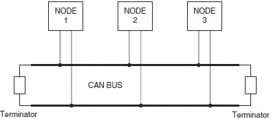
Figure 9.2: Example CAN bus
There are basically two types of CAN protocols: 2.0A and 2.0B. CAN 2.0A is the earlier standard with 11 bits of identifier, while CAN 2.0B is the new extended standard with 29 bits of identifier. 2.0B controllers are completely backward-compatible with 2.0A controllers and can receive and transmit messages in either format.
There are two types of 2.0A controllers. The first is capable of sending and receiving 2.0A messages only, and reception of a 2.0B message will flag an error. The second type of 2.0A controller (known as 2.0B passive) sends and receives 2.0A messages but will also acknowledge receipt of 2.0B messages and then ignore them.
Some of the CAN protocol features are:
• CAN bus is multimaster. When the bus is free, any device attached to the bus can start sending a message.
• CAN bus protocol is flexible. The devices connected to the bus have no addresses, which means messages are not transmitted from one node to another based on addresses. Instead, all nodes in the system receive every message transmitted on the bus, and it is up to each node to decide whether the received message should be kept or discarded. A single message can be destined for a particular node or for many nodes, depending on how the system is designed. Another advantage of having no addresses is that when a device is added to or removed from the bus, no configuration data needs to be changed (i.e., the bus is “hot pluggable”).
• CAN bus offers remote transmit request (RTR), which means that one node on the bus is able to request information from the other nodes. Thus instead of waiting for a node to continuously send information, a request for information can be sent to the node. For example, in a vehicle, where the engine temperature is an important parameter, the system can be designed so the temperature is sent periodically over the bus. However, a more elegant solution is to request the temperature as needed, since it minimizes the bus traffic while maintaining the network’s integrity.
• CAN bus communication speed is not fixed. Any communication speed can be set for the devices attached to a bus.
• All devices on the bus can detect an error. The device that has detected an error immediately notifies all other devices.
• Multiple devices can be connected to the bus at the same time, and there are no logical limits to the number of devices that can be connected. In practice, the number of units that can be attached to a bus is limited by the bus’s delay time and electrical load.
The data on CAN bus is differential and can be in two states: dominant and recessive. Figure 9.3 shows the state of voltages on the bus. The bus defines a logic bit 0 as a dominant bit and a logic bit 1 as a recessive bit. When there is arbitration on the bus, a dominant bit state always wins out over a recessive bit state. In the recessive state, the differential voltage CANH and CANL is less than the minimum threshold (i.e., less than 0.5V receiver input and less than 1.5V transmitter output). In the dominant state, the differential voltage CANH and CANL is greater than the minimum threshold.
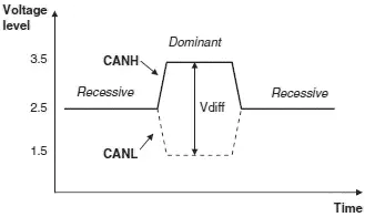
Figure 9.3: CAN logic states
The ISO-11898 CAN bus specifies that a device on that bus must be able to drive a forty-meter cable at 1Mb/s. A much longer bus length can usually be achieved by lowering the bus speed. Figure 9.4 shows the variation of bus length with the communication speed. For example, with a bus length of one thousand meters we can have a maximum speed of 40Kb/s.
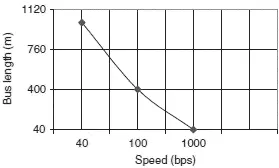
Figure 9.4: CAN bus speed and bus length
A CAN bus is terminated to minimize signal reflections on the bus. The ISO-11898 requires that the bus has a characteristic impedance of 120 ohms. The bus can be terminated by one of the following methods:
• Standard termination
• Split termination
• Biased split termination
In standard termination , the most common termination method, a 120-ohm resistor is used at each end of the bus, as shown in Figure 9.5(a). In split termination, the ends of the bus are split and a single 60-ohm resistor is used as shown in Figure 9.5(b). Split termination allows for reduced emission, and this method is gaining popularity. Biased split termination is similar to split termination except that a voltage divider circuit and a capacitor are used at either end of the bus. This method increases the EMC performance of the bus (Figure 9.5(c)).
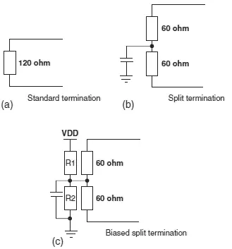
Figure 9.5: Bus termination methods
Many network protocols are described using the seven-layer Open Systems Interconnection (OSI) model. The CAN protocol includes the data link layer, and the physical layer of the OSI reference model (see Figure 9.6). The data link layer (DLL) consists of the Logical Link Control (LLC) and Medium Access Control (MAC). LLC manages the overload notification, acceptance filtering, and recovery management. MAC manages the data encapsulation, frame coding, error detection, and serialization/deserialization of the data. The physical layer consists of the physical signaling layer (PSL), physical medium attachment (PMA), and the medium dependent interface (MDI). PSL manages the bit encoding/decoding and bit timing. PMA manages the driver/receiver characteristics, and MDI is the connections and wires.
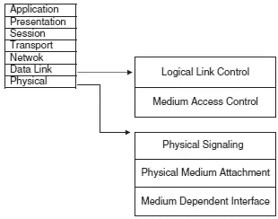
Figure 9.6: CAN and the OSI model
There are basically four message frames in CAN: data, remote, error, and overload. The data and remote frames need to be set by the user. The other two are set by the CAN hardware.
9.1 Data Frame
The data frame is in two formats: standard (having an 11-bit ID) and extended (having a 29-bit ID). The data frame is used by the transmitting device to send data to the receiving device, and the data frame is the most important frame handled by the user. Figure 9.7 shows the data frame’s structure. A standard data frame starts with the start of frame (SOF) bit, which is followed by an 11-bit identifier and the remote transmission request (RTR) bit. The identifier and the RTR form the 12-bit arbitration field. The control field is 6 bits wide and indicates how many bytes of data are in the data field. The data field can be 0 to 8 bytes. The data field is followed by the CRC field, which checks whether or not the received bit sequence is corrupted. The ACK field is 2 bits and is used by the transmitter to receive acknowledgment of a valid frame from any receiver. The end of the message is indicated by a 7-bit end of frame (EOF) field. In an extended data frame, the arbitration field is 32 bits wide (29-bit identifier +1-bit IDE to define the message as an extended data frame +1-bit SRR which is unused +1-bit RTR) (see Figure 9.8).
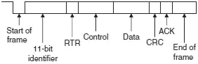
Figure 9.7: Standard data frame
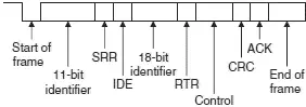
Figure 9.8: Extended data frame
Читать дальшеИнтервал:
Закладка:
Похожие книги на «Advanced PIC Microcontroller Projects in C»
Представляем Вашему вниманию похожие книги на «Advanced PIC Microcontroller Projects in C» списком для выбора. Мы отобрали схожую по названию и смыслу литературу в надежде предоставить читателям больше вариантов отыскать новые, интересные, ещё непрочитанные произведения.


Обсуждение, отзывы о книге «Advanced PIC Microcontroller Projects in C» и просто собственные мнения читателей. Оставьте ваши комментарии, напишите, что Вы думаете о произведении, его смысле или главных героях. Укажите что конкретно понравилось, а что нет, и почему Вы так считаете.