Ibrahim Dogan - Advanced PIC Microcontroller Projects in C
Здесь есть возможность читать онлайн «Ibrahim Dogan - Advanced PIC Microcontroller Projects in C» весь текст электронной книги совершенно бесплатно (целиком полную версию без сокращений). В некоторых случаях можно слушать аудио, скачать через торрент в формате fb2 и присутствует краткое содержание. Город: Burlington, Год выпуска: 2008, ISBN: 2008, Издательство: Elsevier Ltd, Жанр: Программирование, Компьютерное железо, на английском языке. Описание произведения, (предисловие) а так же отзывы посетителей доступны на портале библиотеки ЛибКат.

- Название:Advanced PIC Microcontroller Projects in C
- Автор:
- Издательство:Elsevier Ltd
- Жанр:
- Год:2008
- Город:Burlington
- ISBN:978-0-7506-8611-2
- Рейтинг книги:5 / 5. Голосов: 1
-
Избранное:Добавить в избранное
- Отзывы:
-
Ваша оценка:
Advanced PIC Microcontroller Projects in C: краткое содержание, описание и аннотация
Предлагаем к чтению аннотацию, описание, краткое содержание или предисловие (зависит от того, что написал сам автор книги «Advanced PIC Microcontroller Projects in C»). Если вы не нашли необходимую информацию о книге — напишите в комментариях, мы постараемся отыскать её.
• Features 20 complete, tried and test projects
• Includes a CD-ROM of all the programs, hex listings, diagrams, and data sheets
Advanced PIC Microcontroller Projects in C — читать онлайн бесплатно полную книгу (весь текст) целиком
Ниже представлен текст книги, разбитый по страницам. Система сохранения места последней прочитанной страницы, позволяет с удобством читать онлайн бесплатно книгу «Advanced PIC Microcontroller Projects in C», без необходимости каждый раз заново искать на чём Вы остановились. Поставьте закладку, и сможете в любой момент перейти на страницу, на которой закончили чтение.
Интервал:
Закладка:
• Loop-back mode for self-testing
• Low-power sleep mode
• Interrupt capabilities
The CAN module uses port pins RB3/CANRX and RB2/CANTX for CAN bus receive and transmit functions respectively. These pins are connected to the CAN bus via an MCP2551-type CAN bus transceiver chip.
The PIC18F258 microcontroller supports the following frame types:
• Standard data frame
• Extended data frame
• Remote frame
• Error frame
• Overload frame
• Interframe space
A node uses filters to decide whether or not to accept a received message. Message filtering is applied to the whole identifier field, and mask registers are used to specify which bits in the identifier the filters should examine.
The CAN module in the PIC18F258 microcontroller has six modes of operation:
• Configuration mode
• Disable mode
• Normal operation mode
• Listen-only mode
• Loop-back mode
• Error recognition mode
9.9.1 Configuration Mode
The CAN module is initialized in configuration mode. The module is not allowed to enter configuration mode while a transmission is taking place. In configuration mode the module will neither transmit nor receive, the error counters are cleared, and the interrupt flags remain unchanged.
9.9.2 Disable Mode
In disable mode, the module will neither transmit nor receive. In this mode the internal clock is stopped unless the module is active. If the module is active, it will wait for 11 recessive bits on the CAN bus, detect that condition as an IDLE bus, and then accept the module disable command. The WAKIF interrupt (wake-up interrupt) is the only CAN module interrupt that is active in disable mode.
9.9.3 Normal Operation Mode
The normal operation mode is the CAN module’s standard operating mode. In this mode, the module monitors all bus messages and generates acknowledge bits, error frames, etc. This is the only mode that can transmit messages.
9.9.4 Listen-only Mode
The listen-only mode allows the CAN module to receive messages, including messages with errors. It can be used to monitor bus activities or to detect the baud rate on the bus. For automatic baud rate detection, at least two other nodes must be communicating with each other. The baud rate can be determined by testing different values until valid messages are received. The listen-only mode cannot transmit messages.
9.9.5 Loop-Back Mode
In the loop-back mode, messages can be directed from internal transmit buffers to receive buffers without actually transmitting messages on the CAN bus. This mode is useful during system developing and testing.
9.9.6 Error Recognition Mode
The error recognition mode is used to ignore all errors and receive all messages. In this mode, all messages, valid or invalid are received and copied to the receive buffer.
9.9.7 CAN Message Transmission
The PIC18F258 microcontroller implements three dedicated transmit buffers: TXB0, TXB1, and TXB2. Pending transmittable messages are in a priority queue. Before the SOF is sent, the priorities of all buffers queued for transmission are compared. The transmit buffer with the highest priority is sent first. If two buffers have the same priority, the one with the higher buffer number is sent first. There are four levels of priority.
9.9.8 CAN Message Reception
Reception of a message is a more complex process. The PIC18F258 microcontroller includes two receive buffers, RXB0 and RXB1, with multiple acceptance filters for each (see Figure 9.13). All received messages are assembled in the message assembly buffer (MAB). Once a message is received, regardless of the type of identifier and the number of data bytes, the entire message is copied into the MAB.
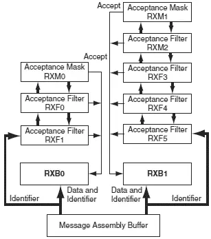
Figure 9.13: Receive buffer block diagram
Received messages have priorities. RXB0 is the higher priority buffer, and it has two message acceptance filters, RXF0 and RXF1. RXB1 is the lower priority buffer and has four acceptance filters: RXF2, RXF3, RXF4, and RXF5. Two programmable acceptance filter masks, RXM0 and RXM1, are also available, one for each receive buffer.
The CAN module uses message acceptance filters and masks to determine if a message in the MAB should be loaded into a receive buffer. Once a valid message is received by the MAB, the identifier field of the message is compared to the filter values. If there is a match, that message is loaded into the appropriate receive buffer. The filter masks determine which bits in the identifier are examined with the filters. The truth table in Table 9.3 shows how each bit in the identifier is compared against the masks and filters to determine if the message should be accepted. If a mask bit is set to 0, that bit in the identifier is automatically accepted regardless of the filter bit.
Table 9.3: Filter/mask truth table
| Mask bit n | Filter bit n | Message identifier bit n001 | Accept or reject bit n |
|---|---|---|---|
| 0 | × | × | Accept |
| 1 | 0 | 0 | Accept |
| 1 | 0 | 1 | Reject |
| 1 | 1 | 0 | Reject |
| 1 | 1 | 1 | Accept |
9.9.9 Calculating the Timing Parameters
Setting the nodes’ timing parameters is essential for the bus to operate reliably. Given the microcontroller clock frequency and the required CAN bus bit rate, we can calculate the values of the following timing parameters:
• Baud rate prescaler value
• Prop_Seg value
• Phase_Seg1 value
• Phase_Seg2 value
• SJW value
Correct timing requires that
• Prop_Seg = Phase_Seg1 ≥ Phase_Seg2
• Phase_Seg2 ≥ SJW
The following example illustrates the calculation of these timing parameters.
Assuming the microcontroller oscillator clock rate is 20MHz and the required CAN bit rate is 125KHz, calculate the timing parameters.
With a 20MHz clock rate, the clock period is 50ns. Choosing a baud rate prescaler value of 4, from Equation (9.4), T Q=2*(BRP+1)*T OSC, gives a time quantum of T Q=500ns. To obtain a nominal bit rate of 125KHz, the nominal bit time must be:
T BIT = 1/0.125MHz = 8μs, or 16T Q
The Sync_Segment is 1T Q. Choosing 2T Qfor the Prop_Seg , and 7T Qfor Phase_Seg1 leaves 6T Qfor Phase_Seg2 and places the sampling point at 10TQ at the end of Phase_Seg1 .
By the rules described earlier, the SJW can be the maximum allowed (i.e., 4). However, a large SJW is only necessary when the clock generation of different nodes is not stable or accurate (e.g., if ceramic resonators are used). Typically, a SJW of 1 is enough. In summary, the required timing parameters are:
Baud rate prescaler (BRP) = 4
Sync_Seg = 1
Prop_Seg = 2
Phase_Seg1 = 7
Phase_Seg2 = 6
SJW = 1
The sampling point is at 10T Qwhich corresponds to 62.5% of the total bit time.
There are several tools available for free on the Internet for calculating CAN bus timing parameters. One such tool is the CAN Baud Rate Calculator, developed by Artic Consultants Ltd (http://www.articconsultants.co.uk). An example using this tool follows.
Assuming the microcontroller oscillator clock rate is 20MHz and the required CAN bit rate is 125KHz, calculate the timing parameters using the CAN Baud Rate Calculator.
Читать дальшеИнтервал:
Закладка:
Похожие книги на «Advanced PIC Microcontroller Projects in C»
Представляем Вашему вниманию похожие книги на «Advanced PIC Microcontroller Projects in C» списком для выбора. Мы отобрали схожую по названию и смыслу литературу в надежде предоставить читателям больше вариантов отыскать новые, интересные, ещё непрочитанные произведения.


Обсуждение, отзывы о книге «Advanced PIC Microcontroller Projects in C» и просто собственные мнения читателей. Оставьте ваши комментарии, напишите, что Вы думаете о произведении, его смысле или главных героях. Укажите что конкретно понравилось, а что нет, и почему Вы так считаете.