Ibrahim Dogan - Advanced PIC Microcontroller Projects in C
Здесь есть возможность читать онлайн «Ibrahim Dogan - Advanced PIC Microcontroller Projects in C» весь текст электронной книги совершенно бесплатно (целиком полную версию без сокращений). В некоторых случаях можно слушать аудио, скачать через торрент в формате fb2 и присутствует краткое содержание. Город: Burlington, Год выпуска: 2008, ISBN: 2008, Издательство: Elsevier Ltd, Жанр: Программирование, Компьютерное железо, на английском языке. Описание произведения, (предисловие) а так же отзывы посетителей доступны на портале библиотеки ЛибКат.

- Название:Advanced PIC Microcontroller Projects in C
- Автор:
- Издательство:Elsevier Ltd
- Жанр:
- Год:2008
- Город:Burlington
- ISBN:978-0-7506-8611-2
- Рейтинг книги:5 / 5. Голосов: 1
-
Избранное:Добавить в избранное
- Отзывы:
-
Ваша оценка:
Advanced PIC Microcontroller Projects in C: краткое содержание, описание и аннотация
Предлагаем к чтению аннотацию, описание, краткое содержание или предисловие (зависит от того, что написал сам автор книги «Advanced PIC Microcontroller Projects in C»). Если вы не нашли необходимую информацию о книге — напишите в комментариях, мы постараемся отыскать её.
• Features 20 complete, tried and test projects
• Includes a CD-ROM of all the programs, hex listings, diagrams, and data sheets
Advanced PIC Microcontroller Projects in C — читать онлайн бесплатно полную книгу (весь текст) целиком
Ниже представлен текст книги, разбитый по страницам. Система сохранения места последней прочитанной страницы, позволяет с удобством читать онлайн бесплатно книгу «Advanced PIC Microcontroller Projects in C», без необходимости каждый раз заново искать на чём Вы остановились. Поставьте закладку, и сможете в любой момент перейти на страницу, на которой закончили чтение.
Интервал:
Закладка:
Code Template is used to generate code in the program. For example, as shown in Figure 5.35, typing switch and pressing CTRL+J automatically generates code for the switch statement. We can add our own templates by selecting Tools→Options→Auto Complete . Some of the available templates are array, switch, for , and if .
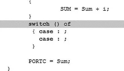
Figure 5.35: Using the Code Template
Auto Correct corrects typing mistakes automatically. A new list of recognized words can be added by selecting Tools→Options→Auto Correct Tab.
Bookmarks make the navigation easier in large code. We can set bookmarks by entering CTRL+SHIFT+number, and can then jump to the bookmark by pressing CTRL+number, where number is the bookmark number.
The bottom section of the screen, also called the Message Window, consists of three tabs: Messages, Find , and QConverter . Compilation errors and warnings are reported under the Messages tab. Double-clicking on a message line highlights the line where the error occurred. A HEX file can be generated only if the source file contains no errors. Figure 5.36 shows the results of a successful compilation listed in the Message Window. The QConverter tab can be used to convert decimal numbers into binary or hexadecimal, and vice versa.
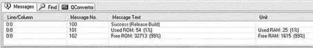
Figure 5.36: Display of a successful compilation
5.3.2 Creating and Compiling a New File
mikroC files are organized into projects, and all files for a single project are stored in the same folder. By default, a project file has the extension “.ppc”. A project file contains the project name, the target microcontroller device, device configuration flags, the device clock, and list of source files with their paths. C source files have the extension “.c”.
The following example illustrates step-by-step how to create and compile a program source file.
Write a C program to calculate the sum of the integer numbers 1 to 10 and then send the result to PORTC of a PIC18F452-type microcontroller. Assume that eight LEDs are connected to the microcontroller’s PORTC via current limiting resistors. Draw the circuit diagram and show the steps involved in creating and compiling the program.
Figure 5.37 shows the circuit diagram of the project. The LEDs are connected to PORTC using 390 ohm current limiting resistors. The microcontroller is operated from a 4MHz resonator.
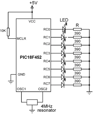
Figure 5.37: Circuit diagram of the project
The program is created and compiled as follows:
Step 1 Double-click the mikroC icon to start the IDE.
Step 2 Create a new project called EXAMPLE. Click Project→New Project and fill in the form, as shown in Figure 5.38, by selecting the device type, the clock, and the configuration fuse.
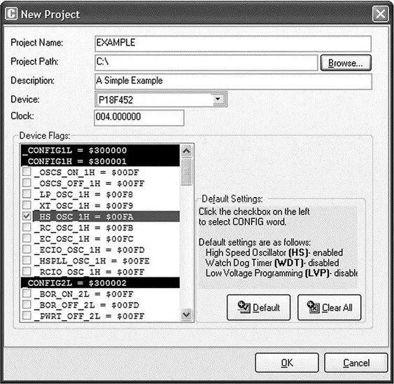
Figure 5.38: Creating a new project
Step 3 Enter the following program into the Code Editor section of the IDE:
/**********************************************************************
EXAMPLE PROGRAM
8 LEDs are connected to a PIC18F452 type microcontroller.
This program calculates the sum of integer numbers from 1 to 10
And then displays the sum on PORTC of the microcontroller.
Author: Dogan Ibrahim
File: EXAMPLE.C
**********************************************************************/
void main() {
unsigned int Sum,i;
TRISC = 0;
Sum = 0;
for(i=1; i<=10; i++) {
Sum = Sum + i;
}
PORTC = Sum;
}
Step 4 Save the program with the name EXAMPLE by clicking File→Save As . The program will be saved with the name EXAMPLE.C.
Step 5 Compile the project by pressing CTRL+F9 or by clicking the Build Project button (see Figure 5.39).
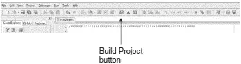
Figure 5.39: Build Project button
Step 6 If the compilation is successful, a Success message will appear in the Message Window as shown in Figure 5.36. Any program errors will appear in the Message Window and should be corrected before the project proceeds further. The compiler generates a number of output files, which can be selected by clicking Tools→Options→Output . The various output files include:
.ASM file This is the assembly file of the program. Figure 5.40 shows the EXAMPLE.ASM file.
; ASM code generated by mikroVirtualMachine for PIC - V. 6.2.1.0
; Date/Time: 07/07/2007 16:46:12
; Info: http://www.mikroelektronika.co.yu
; ADDRESS OPCODE ASM
; ----------------------------------------------
$0000 $EF04 F000 GOTO _main
$0008 $ _main:
;EXAMPLE.c,14 :: void main()
;EXAMPLE.c,18 :: TRISC = 0;
$0008 $6A94 CLRF TRISC, 0
;EXAMPLES.c,20 :: Sum = 0;
$000A $6A15 CLRF main_Sum_L0, 0
$000C $6A16 CLRF main_Sum_L0+1, 0
;EXAMPLE.c,21 :: for(i=1; i <= 10; i++)
$000E $0E01 MOVLW 1
$0010 $6E17 MOVWF main_i_L0, 0
$0012 $0E00 MOVLW 0
$0014 $6E18 MOVWF main_i_L0+1, 0
$0016 $ L_main_0:
$0016 $0E00 MOVLW 0
$0018 $6E00 MOVWF STACK_0, 0
$001A $5018 MOVF main_i_L0+1, 0, 0
$001C $5C00 SUBWF STACK_0, 0, 0
$001E $E102 BNZ L_main_3
$0020 $5017 MOVF main_i_L0, 0, 0
$0022 $080A SUBLW 10
$0024 $ L_main_3:
$0024 $E307 BNC L_main_1
;EXAMPLE.c,23 :: SUM = Sum + i;
$0026 $5017 MOVF main_i_L0, 0, 0
$0028 $2615 ADDWF main_Sum_L0, 1, 0
$002A $5018 MOVF main_i_L0+1, 0, 0
$002C $2216 ADDWFC main_Sum_L0+1, 1, 0
;EXAMPLE.c,24 :: }
$002E $ L_main_2:
;EXAMPLE.c,21 :: for(i=1; i <= 10; i++)
$002E $4A17 INFSNZ main_i_L0, 1, 0
$0030 $2A18 INCF main_i_L0+1, 1, 0
;EXAMPLE.c,24 :: }
$0032 $D7F1 BRA L_main_0
$0034 $ L_main_1:
;EXAMPLE.c,26 :: PORTC = Sum;
$0034 $C015 FF82 MOVFF main_Sum_L0, PORTC
;EXAMPLE.c,27 :: }
$0038 $D7FF BRA $

Figure 5.40: EXAMPLE.ASM
.LST file This is the listing file of the program. Figure 5.41 shows the EXAMPLE.LST file.
; ASM code generated by mikroVirtualMachine for PIC - V. 6.2.1.0
Интервал:
Закладка:
Похожие книги на «Advanced PIC Microcontroller Projects in C»
Представляем Вашему вниманию похожие книги на «Advanced PIC Microcontroller Projects in C» списком для выбора. Мы отобрали схожую по названию и смыслу литературу в надежде предоставить читателям больше вариантов отыскать новые, интересные, ещё непрочитанные произведения.


Обсуждение, отзывы о книге «Advanced PIC Microcontroller Projects in C» и просто собственные мнения читателей. Оставьте ваши комментарии, напишите, что Вы думаете о произведении, его смысле или главных героях. Укажите что конкретно понравилось, а что нет, и почему Вы так считаете.