Ibrahim Dogan - Advanced PIC Microcontroller Projects in C
Здесь есть возможность читать онлайн «Ibrahim Dogan - Advanced PIC Microcontroller Projects in C» весь текст электронной книги совершенно бесплатно (целиком полную версию без сокращений). В некоторых случаях можно слушать аудио, скачать через торрент в формате fb2 и присутствует краткое содержание. Город: Burlington, Год выпуска: 2008, ISBN: 2008, Издательство: Elsevier Ltd, Жанр: Программирование, Компьютерное железо, на английском языке. Описание произведения, (предисловие) а так же отзывы посетителей доступны на портале библиотеки ЛибКат.

- Название:Advanced PIC Microcontroller Projects in C
- Автор:
- Издательство:Elsevier Ltd
- Жанр:
- Год:2008
- Город:Burlington
- ISBN:978-0-7506-8611-2
- Рейтинг книги:5 / 5. Голосов: 1
-
Избранное:Добавить в избранное
- Отзывы:
-
Ваша оценка:
Advanced PIC Microcontroller Projects in C: краткое содержание, описание и аннотация
Предлагаем к чтению аннотацию, описание, краткое содержание или предисловие (зависит от того, что написал сам автор книги «Advanced PIC Microcontroller Projects in C»). Если вы не нашли необходимую информацию о книге — напишите в комментариях, мы постараемся отыскать её.
• Features 20 complete, tried and test projects
• Includes a CD-ROM of all the programs, hex listings, diagrams, and data sheets
Advanced PIC Microcontroller Projects in C — читать онлайн бесплатно полную книгу (весь текст) целиком
Ниже представлен текст книги, разбитый по страницам. Система сохранения места последней прочитанной страницы, позволяет с удобством читать онлайн бесплатно книгу «Advanced PIC Microcontroller Projects in C», без необходимости каждый раз заново искать на чём Вы остановились. Поставьте закладку, и сможете в любой момент перейти на страницу, на которой закончили чтение.
Интервал:
Закладка:
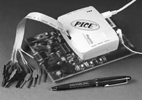
Figure 5.23: PICE-MC in-circuit emulator
5.2.5 Breadboards
Building an electronic circuit requires connecting the components as shown in the relevant circuit diagram, usually by soldering the components together on a strip board or a printed circuit board (PCB). This approach is appropriate for circuits that have been tested and are functioning as desired, and also when the circuit is being made permanent. However, making a PCB design for just a few applications — for instance, while still developing the circuit — is not economical.
Instead, while the circuit is still under development, the components are usually assembled on a solderless breadboard. A typical breadboard (see Figure 5.24) consists of rows and columns of holes spaced so that integrated circuits and other components can be fitted inside them. The holes have spring actions so the component leads are held tightly in place. There are various types and sizes of breadboards, suitable for circuits of different complexities. Breadboards can also be stacked together to make larger boards for very complex circuits. Figure 5.25 shows the internal connection layout of the breadboard in Figure 5.24.
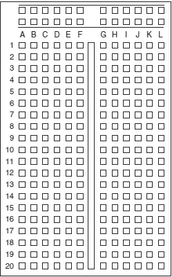
Figure 5.24: A typical breadboard layout
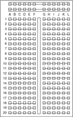
Figure 5.25: Internal wiring of the breadboard in Figure 5.24
The top and bottom halves of the breadboard are entirely separate. Columns 1 to 20 in rows A to F are connected to each other on a column basis. Rows G to L in columns 1 to 20 are likewise connected to each other on a column basis. Integrated circuits are placed such that the legs on one side are on the top half of the breadboard, and the legs on the other side are on the bottom half. The two columns on the far left of the board are usually reserved for the power and ground connections. Connections between components are usually made with stranded (or solid) wires plugged into the holes to be connected.
Figure 5.26 shows a breadboard holding two integrated circuits and a number of resistors and capacitors.
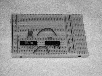
Figure 5.26: Picture of a breadboard with some components
The nice thing about breadboard design is that the circuit can be modified easily and quickly, and ideas can be tested without having to solder the components. Once a circuit has been tested and is working satisfactorily, the components are easily removed and the breadboard can be used for other projects.
5.3 mikroC Integrated Development Environment (IDE)
In this book we are using the mikroC compiler developed by mikroElektronika. Before using this compiler, we need to know how the mikroC integrated development environment (IDE) is organized and how to write, compile, and simulate a program in the mikroC language. In this section we will look at the operation of the mikroC IDE in detail.
A free 2K program size limited version of the mikroC IDE, available on the mikroElektronika web site (www.mikroe.com), is adequate for most small or medium-sized applications. Alternatively, you can purchase a license and turn the limited version into a fully working, unlimited IDE to use for projects of any size and complexity.
After installing the mikroC IDE, a new icon should appear by default on your desktop. Double-click this icon to start the IDE.
5.3.1 mikroC IDE Screen
After the mikroC icon is double-clicked to start the IDE, the screen shown in Figure 5.27 is displayed by default.
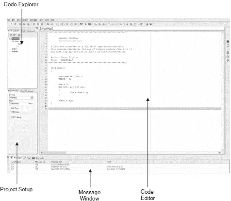
Figure 5.27: mikroC IDE screen
The screen is divided into four areas: the top-left section, the bottom-left section, the middle section, and the bottom section.
The top left, the Code Explorer section, displays every declared item in the source code. In the example in Figure 5.28, main is listed under Functions and variables Sum and i are listed under main .
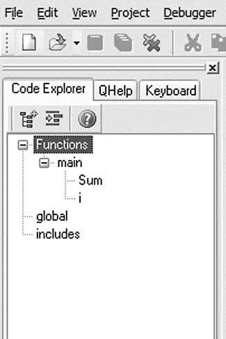
Figure 5.28: Code Explorer form
There are two additional tabs in the Code Explorer. As shown in Figure 5.29, the QHelp tab lists all the available built-in functions and library functions for a quick reference.
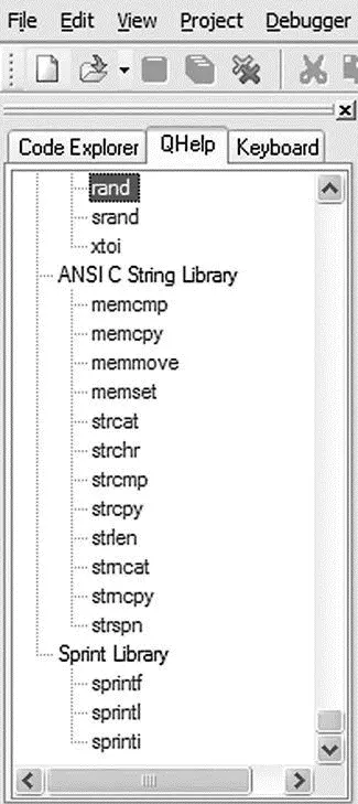
Figure 5.29: QHelp form
The Keyboard tab lists all the available keyboard shortcuts in mikroC IDE (see Figure 5.30).
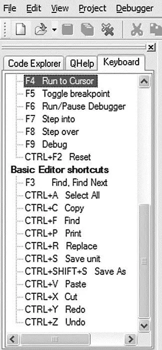
Figure 5.30: Keyboard form
In the bottom-left section, called Project Setup (see Figure 5.31), the microcontroller device type, clock rate, and build type are specified. The build type can be either Release , which is the normal compiler operating mode, or ICD debug , if the program is to be debugged using the in-circuit debugger.
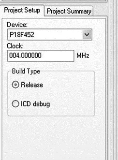
Figure 5.31: Project setup form
The Project Setup section has a tab called Project Summary which lists all the types of files used in the project, as shown in Figure 5.32.
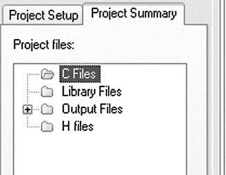
Figure 5.32: Project summary form
The middle section is the Code Editor, an advanced text editor. Programs are written in this section of the screen. The Code Editor supports:
• Code Assistant
• Parameter Assistant
• Code Template
• Auto Correct
• Bookmarks
The Code Assistant is useful when writing a program. Type the first few letters of an identifier and then press the CTRL+SPACE keys to list all valid identifiers beginning with those letters. In Figure 5.33, for example, to locate identifier strlen , the letters str are typed and CTRL+SPACE is pressed. strlen can be selected from the displayed list of matching valid words by using keyboard arrows and pressing ENTER.
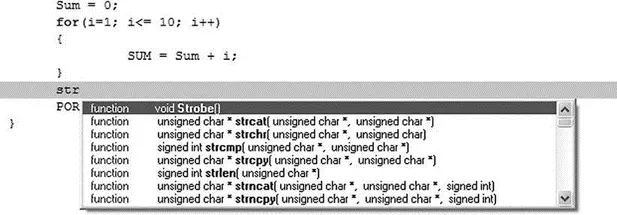
Figure 5.33: Using the Code Assistant
The Parameter Assistant is invoked when a parenthesis is opened after a function or a procedure name. The expected parameters are listed in a small window just above the parenthesis. In Figure 5.34, function strlen has been entered, and unsigned char *s appears in a small window when a parenthesis is opened.
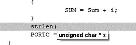
Figure 5.34: Using the Parameter Assistant
Читать дальшеИнтервал:
Закладка:
Похожие книги на «Advanced PIC Microcontroller Projects in C»
Представляем Вашему вниманию похожие книги на «Advanced PIC Microcontroller Projects in C» списком для выбора. Мы отобрали схожую по названию и смыслу литературу в надежде предоставить читателям больше вариантов отыскать новые, интересные, ещё непрочитанные произведения.


Обсуждение, отзывы о книге «Advanced PIC Microcontroller Projects in C» и просто собственные мнения читателей. Оставьте ваши комментарии, напишите, что Вы думаете о произведении, его смысле или главных героях. Укажите что конкретно понравилось, а что нет, и почему Вы так считаете.