Ibrahim Dogan - Advanced PIC Microcontroller Projects in C
Здесь есть возможность читать онлайн «Ibrahim Dogan - Advanced PIC Microcontroller Projects in C» весь текст электронной книги совершенно бесплатно (целиком полную версию без сокращений). В некоторых случаях можно слушать аудио, скачать через торрент в формате fb2 и присутствует краткое содержание. Город: Burlington, Год выпуска: 2008, ISBN: 2008, Издательство: Elsevier Ltd, Жанр: Программирование, Компьютерное железо, на английском языке. Описание произведения, (предисловие) а так же отзывы посетителей доступны на портале библиотеки ЛибКат.

- Название:Advanced PIC Microcontroller Projects in C
- Автор:
- Издательство:Elsevier Ltd
- Жанр:
- Год:2008
- Город:Burlington
- ISBN:978-0-7506-8611-2
- Рейтинг книги:5 / 5. Голосов: 1
-
Избранное:Добавить в избранное
- Отзывы:
-
Ваша оценка:
Advanced PIC Microcontroller Projects in C: краткое содержание, описание и аннотация
Предлагаем к чтению аннотацию, описание, краткое содержание или предисловие (зависит от того, что написал сам автор книги «Advanced PIC Microcontroller Projects in C»). Если вы не нашли необходимую информацию о книге — напишите в комментариях, мы постараемся отыскать её.
• Features 20 complete, tried and test projects
• Includes a CD-ROM of all the programs, hex listings, diagrams, and data sheets
Advanced PIC Microcontroller Projects in C — читать онлайн бесплатно полную книгу (весь текст) целиком
Ниже представлен текст книги, разбитый по страницам. Система сохранения места последней прочитанной страницы, позволяет с удобством читать онлайн бесплатно книгу «Advanced PIC Microcontroller Projects in C», без необходимости каждый раз заново искать на чём Вы остановились. Поставьте закладку, и сможете в любой момент перейти на страницу, на которой закончили чтение.
Интервал:
Закладка:
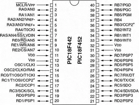
Figure 2.1: PIC18F452 microcontroller DIP pin configuration
Figure 2.2 shows the internal block diagram of the PIC18F452 microcontroller. The CPU is at the center of the diagram and consists of an 8-bit ALU, an 8-bit working accumulator register (WREG), and an 8×8 hardware multiplier. The higher byte and the lower byte of a multiplication are stored in two 8-bit registers called PRODH and PRODL respectively.
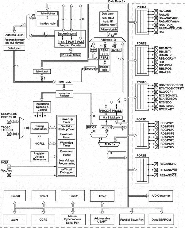
Figure 2.2: Block diagram of the PIC18F452 microcontroller
The program counter and program memory are shown in the upper left portion of the diagram. Program memory addresses consist of 21 bits, capable of accessing 2Mbytes of program memory locations. The PIC18F452 has only 32Kbytes of program memory, which requires only 15 bits. The remaining 6 address bits are redundant and not used. A table pointer provides access to tables and to the data stored in program memory. The program memory contains a 31-level stack which is normally used to store the interrupt and subroutine return addresses.
The data memory can be seen at the top center of the diagram. The data memory bus is 12 bits wide, capable of accessing 4Kbytes of data memory locations. As we shall see later, the data memory consists of special function registers (SFR) and general purpose registers, all organized in banks.
The bottom portion of the diagram shows the timers/counters, capture/compare/PWM registers, USART, A/D converter, and EEPROM data memory. The PIC18F452 consists of:
• 4 timers/counters
• 2 capture/compare/PWM modules
• 2 serial communication modules
• 8 10-bit A/D converter channels
• 256 bytes EEPROM
The oscillator circuit, located at the left side of the diagram, consists of:
• Power-up timer
• Oscillator start-up timer
• Power-on reset
• Watchdog timer
• Brown-out reset
• Low-voltage programming
• In-circuit debugger
• PLL circuit
• Timing generation circuit
The PLL circuit is new to the PIC18F series and provides the option of multiplying up the oscillator frequency to speed up the overall operation. The watchdog timer can be used to force a restart of the microcontroller in the event of a program crash. The in-circuit debugger is useful during program development and can be used to return diagnostic data, including the register values, as the microcontroller is executing a program.
The input-output ports are located at the right side of the diagram. The PIC18F452 has five parallel ports named PORTA, PORTB, PORTC, PORTD, and PORTE. Most port pins have multiple functions. For example, PORTA pins can be used as parallel inputs-outputs or analog inputs. PORTB pins can be used as parallel inputs-outputs or as interrupt inputs.
2.1.1 Program Memory Organization
The program memory map is shown in Figure 2.3. All PIC18F devices have a 21-bit program counter and hence are capable of addressing 2Mbytes of memory space. User memory space on the PIC18F452 microcontroller is 00000H to 7FFFH. Accessing a nonexistent memory location (8000H to 1FFFFFH) will cause a read of all 0s. The reset vector, where the program starts after a reset, is at address 0000. Addresses 0008H and 0018H are reserved for the vectors of high-priority and low-priority interrupts respectively, and interrupt service routines must be written to start at one of these locations.
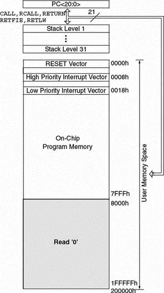
Figure 2.3: Program memory map of PIC18F452
The PIC18F microcontroller has a 31-entry stack that is used to hold the return addresses for subroutine calls and interrupt processing. The stack is not part of the program or the data memory space. The stack is controlled by a 5-bit stack pointer which is initialized to 00000 after a reset. During a subroutine call (or interrupt) the stack pointer is first incremented, and the memory location it points to is written with the contents of the program counter. During the return from a subroutine call (or interrupt), the memory location the stack pointer has pointed to is decremented. The projects in this book are based on using the C language. Since subroutine and interrupt call/return operations are handled automatically by the C language compiler, their operation is not described here in more detail.
Program memory is addressed in bytes, and instructions are stored as two bytes or four bytes in program memory. The least significant byte of an instruction word is always stored in an even address of the program memory.
An instruction cycle consists of four cycles: A fetch cycle begins with the program counter incrementing in Q1. In the execution cycle, the fetched instruction is latched into the instruction register in cycle Q1. This instruction is decoded and executed during cycles Q2, Q3, and Q4. A data memory location is read during the Q2 cycle and written during the Q4 cycle.
2.1.2 Data Memory Organization
The data memory map of the PIC18F452 microcontroller is shown in Figure 2.4. The data memory address bus is 12 bits with the capability to address up to 4Mbytes. The memory in general consists of sixteen banks, each of 256 bytes, where only 6 banks are used. The PIC18F452 has 1536 bytes of data memory (6 banks × 256 bytes each) occupying the lower end of the data memory. Bank switching happens automatically when a high-level language compiler is used, and thus the user need not worry about selecting memory banks during programming.
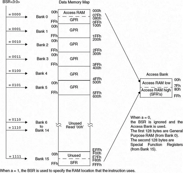
Figure 2.4: The PIC18F452 data memory map
The special function register (SFR) occupies the upper half of the top memory bank. SFR contains registers which control operations such as peripheral devices, timers/counters, A/D converter, interrupts, and USART. Figure 2.5 shows the SFR registers of the PIC18F452 microcontroller.
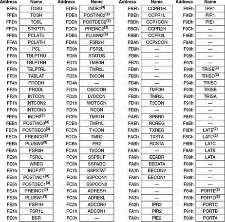
Figure 2.5: The PIC18F452 SFR registers
2.1.3 The Configuration Registers
PIC18F452 microcontrollers have a set of configuration registers (PIC16-series microcontrollers had only one configuration register). Configuration registers are programmed during the programming of the flash program memory by the programming device. These registers are shown in Table 2.2. these registers are given in Table 2.3. Some of the more important configuration registers are described in this section in detail.
Table 2.2: PIC18F452 configuration registers
| File Name | Bit 7 | Bit 6 | Bit 5 | Bit 4 | Bit 3 | Bit 2 | Bit 1 | Bit 0 | Default/Unprogrammed Value | |
|---|---|---|---|---|---|---|---|---|---|---|
| 300001h | CONFIG1H | — | — | OSCSEN# | — | — | FOSC2 | FOSC1 | FOSC0 | --1--111 |
| 300002h | CONFIG2L | — | — | — | — | BORV1 | BORV0 | BOREN | PWRTEN# | ---- 1111 |
| 300003h | CONFIG2H | — | — | — | — | WDTPS2 | WDTPS1 | WDTPS0 | WDTEN | ---- 1111 |
| 300005h | CONFIG3H | — | — | — | — | — | — | — | CCP2MX | ---- ---1 |
| 300006h | CONFIG4L | DEBUG | — | — | — | — | LVP | — | STVREN1 | --- -1-1 |
| 300008h | CONFIG5L | — | — | — | — | CP3 | CP2 | CP1 | CP0 | ---- 1111 |
| 300009h | CONFIG5H | CPD | CPB | — | — | — | — | — | — | 11-- ---- |
| 30000Ah | CONFIG6L | — | — | — | — | WRT3 | WRT2 | WRT1 | WRT0 | ---- 1111 |
| 30000Bh | CONFIG6H | WRTD | WRTB | WRTC | — | — | — | — | — | 111- ---- |
| 30000Ch | CONFIG7L | — | — | — | — | EBTR3 | EBTR2 | EBTR1 | EBTR0 | ---- 1111 |
| 30000Dh | CONFIG7H | — | EBTRB | — | — | — | — | — | — | -1----- |
| 3FFFFEh | DEVID1 | DEV2 | DEV1 | DEV0 | REV4 | REV3 | REV2 | REV1 | REV0 | (1) |
| 3FFFFFh | DEVID2 | DEV10 | DEV9 | DEV8 | DEV7 | DEV6 | DEV5 | DEV4 | DEV3 | 0000 0100 |
Legend: x = unknown, u = unchanged, – = unimplemented, q = value depends on condition. Shaded cells are unimplemented, read as ‘0’.
Читать дальшеИнтервал:
Закладка:
Похожие книги на «Advanced PIC Microcontroller Projects in C»
Представляем Вашему вниманию похожие книги на «Advanced PIC Microcontroller Projects in C» списком для выбора. Мы отобрали схожую по названию и смыслу литературу в надежде предоставить читателям больше вариантов отыскать новые, интересные, ещё непрочитанные произведения.


Обсуждение, отзывы о книге «Advanced PIC Microcontroller Projects in C» и просто собственные мнения читателей. Оставьте ваши комментарии, напишите, что Вы думаете о произведении, его смысле или главных героях. Укажите что конкретно понравилось, а что нет, и почему Вы так считаете.