Qing Li - Real-Time Concepts for Embedded Systems
Здесь есть возможность читать онлайн «Qing Li - Real-Time Concepts for Embedded Systems» весь текст электронной книги совершенно бесплатно (целиком полную версию без сокращений). В некоторых случаях можно слушать аудио, скачать через торрент в формате fb2 и присутствует краткое содержание. Город: San Francisco, Год выпуска: 2003, ISBN: 2003, Издательство: CMP books, Жанр: ОС и Сети, на английском языке. Описание произведения, (предисловие) а так же отзывы посетителей доступны на портале библиотеки ЛибКат.
- Название:Real-Time Concepts for Embedded Systems
- Автор:
- Издательство:CMP books
- Жанр:
- Год:2003
- Город:San Francisco
- ISBN:1-57820-124-1
- Рейтинг книги:4 / 5. Голосов: 1
-
Избранное:Добавить в избранное
- Отзывы:
-
Ваша оценка:
Real-Time Concepts for Embedded Systems: краткое содержание, описание и аннотация
Предлагаем к чтению аннотацию, описание, краткое содержание или предисловие (зависит от того, что написал сам автор книги «Real-Time Concepts for Embedded Systems»). Если вы не нашли необходимую информацию о книге — напишите в комментариях, мы постараемся отыскать её.
Delve into the details of real-time programming so you can develop a working knowledge of the common design patterns and program structures of real-time operating systems (RTOS). The objects and services that are a part of most RTOS kernels are described and real-time system design is explored in detail. You learn how to decompose an application into units and how to combine these units with other objects and services to create standard building blocks. A rich set of ready-to-use, embedded design “building blocks” is also supplied to accelerate your development efforts and increase your productivity.
Experienced developers new to embedded systems and engineering or computer science students will both appreciate the careful balance between theory, illustrations, and practical discussions. Hard-won insights and experiences shed new light on application development, common design problems, and solutions in the embedded space. Technical managers active in software design reviews of real-time embedded systems will find this a valuable reference to the design and implementation phases.
Qing Li is a senior architect at Wind River Systems, Inc., and the lead architect of the company’s embedded IPv6 products. Qing holds four patents pending in the embedded kernel and networking protocol design areas. His 12+ years in engineering include expertise as a principal engineer designing and developing protocol stacks and embedded applications for the telecommunications and networks arena. Qing was one of a four-member Silicon Valley startup that designed and developed proprietary algorithms and applications for embedded biometric devices in the security industry.
Caroline Yao has more than 15 years of high tech experience ranging from development, project and product management, product marketing, business development, and strategic alliances. She is co-inventor of a pending patent and recently served as the director of partner solutions for Wind River Systems, Inc. About the Authors
Real-Time Concepts for Embedded Systems — читать онлайн бесплатно полную книгу (весь текст) целиком
Ниже представлен текст книги, разбитый по страницам. Система сохранения места последней прочитанной страницы, позволяет с удобством читать онлайн бесплатно книгу «Real-Time Concepts for Embedded Systems», без необходимости каждый раз заново искать на чём Вы остановились. Поставьте закладку, и сможете в любой момент перейти на страницу, на которой закончили чтение.
Интервал:
Закладка:
As shown in Figure 15.17, task #1 is the data producer, while task #2 is the consumer. Task #1 can introduce data into the buffer as long as the task can successfully acquire the counting semaphore. The counting semaphore may be initialized to a value less than the maximum allowable token value. Task #2 can increase the token value with the give operation and may decrease the token value by the take operation depending on how fast the task can consume data. Listing 15.2 shows the pseudo code for this design pattern.
Listing 15.2: Pseudo code for data transfer with flow control.
data producing task
Acquire(Counting_Semaphore)
Produce data into msgQueue
data consuming task
Consume data from MsgQueue
Give(Counting_Semaphore)
15.7.2 Asynchronous Data Reception from Multiple Data Communication Channels
Commonly, a daemon task receives data from multiple input sources, which implies that data arrives on multiple message queues. A task cannot block and wait for data on multiple message queues. Therefore, in such cases, multiple sources may use a single semaphore to signal the arrival of data. A task cannot block and wait on multiple semaphores either.
The task blocks and waits on the semaphore. Each ISR inserts data in the corresponding message queue followed by a give operation on the semaphore.
As shown in Figure 15.18, a single interrupt lock is sufficient to protect against multiple interrupt sources, as long as the masked interrupt level covers these sources. Both the interrupt service routines use a single semaphore as the signal channel.
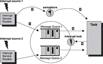
Figure 15.18: Task waiting on multiple input sources.
Listing 15.3 shows the code that the task runs when multiple input message queues are present. Note that the semaphore used in this case is a binary semaphore.
Listing 15.3: Pseudo code for task waiting on multiple input sources.
while (Get(Binary_Semaphore))
disable(interrupts)
for (each msgQueue)
get msgQueueLength
for (msgQueueLength)
remove a message
enable(interrupts)
process the message
disable(interrupts)
endfor
endfor
enable(interrupts)
end while
Some RTOS kernels do not have the event-register object. Implementing the event register using the common basic primitives found in the majority of the RTOS kernels can be quite useful when porting applications from one RTOS to another.
The event-register object can be implemented using a shared variable, an interrupt lock, and a semaphore. The shared variable stores and retrieves the events. The interrupt lock guards the shared variable because ISRs can generate events through the event register. The semaphore blocks the task wanting to receive desired events.
Event_Receive(wanted_events) {
task_cb.wanted_events = wanted_events
While (TRUE)
Get(task_cb.event_semaphore)
disable(interrupts)
events = wanted_events XOR task_cb.recvd_events
task_cb.wanted_events = task_cb.wanted_event AND (NOT events)
enable(interrupts)
If (events is not empty)
return (events)
endIf
EndWhile
}
The variable task_cb refers to the task control block, in which the kernel keeps its private, task-specific information. Note that the unwanted events are not cleared because the task can call event_receive some time later.
Event_Send(events) {
disable(interrupts)
task_cb.recvd_events = task_cb.recvd_events OR events
enable(interrupts)
Give(task_cb.event_semaphore)
}
15.7.3 Multiple Input Communication Channels
A daemon task usually has multiple data input sources and multiple event input sources, as shown in Figure 15.19. Consider a daemon task that processes data from an I/O device and has a periodic timer, which is used for recovery if the device is stuck in an inconsistent state. The system timer ISR signals the periodic timer event; this event does not carry data. In such situations, an event register combined with a counting semaphore is a much better alternative than using counting semaphores alone for signaling (see Figure 15.10).
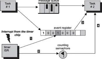
Figure 15.19: Task with multiple input communication channels.
With an event register, each event bit is pre-allocated to a source. In this design pattern, one event bit is assigned to the I/O task #1 and another bit is assigned to the timer ISR. The task blocks on an event register, and an event from either source activates the task. The I/O task first inserts the data associated with an I/O device into the message queue. Then the I/O task signals this event to the task by setting the event's assigned bit in the event register. The timer ISR sets the event bit; this event is no more than a tick announcement to the task. After the task resumes execution, it performs the appropriate action according to the event-register state.
Because the event register is only used as a signaling mechanism, a counting semaphore is used to keep track of the total number of tick occurrences. Listing 15.4 puts this discussion into perspective. The addition of the counting semaphore does not increase the code complexity.
Listing 15.4: Pseudo code for using a counting semaphore for event accumulation combined with an event-register used for event notification.
while (the_events = wait for events from Event-Register)
if (the_events& EVENT_TYPE_DEVICE)
while (Get message from msgQueue)
process the message
endwhile
endif
if (the_events& EVENT_TYPE_TIMER)
counter = 0
disable(interrupts)
while (Get(Counting_Semaphore))
counter = counter + 1
endwhile
enable(interrupts)
if (counter › 1)
recovery time
else
process the timer tick
endif
endif
endwhile
15.7.4 Using Condition Variables to Synchronize between Readers and Writers
The design pattern shown in Figure 15.20 demonstrates the use of condition variables. A condition variable can be associated with the state of a shared resource. In this example, multiple tasks are trying to insert messages into a shared message queue. The predicate of the condition variable is 'the message queue is full.' Each writer task tries first to insert the message into the message queue. The task waits (and is blocked) if the message queue is currently full. Otherwise, the message is inserted, and the task continues its execution path.
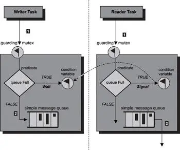
Figure 15.20: Using condition variables for task synchronization.
Note the message queue shown in Figure 15.20 is called a 'simple message queue.' For the sake of this example, the reader should assume this message queue is a simple buffer with structured content. This simple message queue is not the same type of message queue that is provided by the RTOS.
Читать дальшеИнтервал:
Закладка:
Похожие книги на «Real-Time Concepts for Embedded Systems»
Представляем Вашему вниманию похожие книги на «Real-Time Concepts for Embedded Systems» списком для выбора. Мы отобрали схожую по названию и смыслу литературу в надежде предоставить читателям больше вариантов отыскать новые, интересные, ещё непрочитанные произведения.


Обсуждение, отзывы о книге «Real-Time Concepts for Embedded Systems» и просто собственные мнения читателей. Оставьте ваши комментарии, напишите, что Вы думаете о произведении, его смысле или главных героях. Укажите что конкретно понравилось, а что нет, и почему Вы так считаете.