John Crisp - Introduction to Microprocessors and Microcontrollers
Здесь есть возможность читать онлайн «John Crisp - Introduction to Microprocessors and Microcontrollers» весь текст электронной книги совершенно бесплатно (целиком полную версию без сокращений). В некоторых случаях можно слушать аудио, скачать через торрент в формате fb2 и присутствует краткое содержание. Год выпуска: 2004, ISBN: 2004, Издательство: Elsevier, Жанр: Компьютерное железо, на английском языке. Описание произведения, (предисловие) а так же отзывы посетителей доступны на портале библиотеки ЛибКат.
- Название:Introduction to Microprocessors and Microcontrollers
- Автор:
- Издательство:Elsevier
- Жанр:
- Год:2004
- ISBN:0-7506-5989-0
- Рейтинг книги:3 / 5. Голосов: 1
-
Избранное:Добавить в избранное
- Отзывы:
-
Ваша оценка:
Introduction to Microprocessors and Microcontrollers: краткое содержание, описание и аннотация
Предлагаем к чтению аннотацию, описание, краткое содержание или предисловие (зависит от того, что написал сам автор книги «Introduction to Microprocessors and Microcontrollers»). Если вы не нашли необходимую информацию о книге — напишите в комментариях, мы постараемся отыскать её.
Introduction to Microprocessors and Microcontrollers — читать онлайн бесплатно полную книгу (весь текст) целиком
Ниже представлен текст книги, разбитый по страницам. Система сохранения места последней прочитанной страницы, позволяет с удобством читать онлайн бесплатно книгу «Introduction to Microprocessors and Microcontrollers», без необходимости каждый раз заново искать на чём Вы остановились. Поставьте закладку, и сможете в любой момент перейти на страницу, на которой закончили чтение.
Интервал:
Закладка:
Status register
This is very similar to the one we met when looking at the Z80 in Chapter 8.
The bits are:
Bit 0 is the C(carry/borrow) bit. 1 = a carry out from the MSB (most significant bit) of the result otherwise it is cleared to zero. For ‘borrow’ the values are reversed. Subtraction is carried out using the two’s-complement method that we met in Chapter 4.
Bit 1 reflects the carry situation that last occurred from the 4th bit of the result. This is also called the half-carry bit.
Bit 2 is the zero flag. It is set to ONE when the result of the last arithmetic or logic operation is ZERO. Be careful not to misread this.
Bit 3 goes to 0 after running the SLEEP instruction.
Bit 4 goes to 0 when a watchdog time-out has occurred.
Bit 5 is used to select between the two memory banks. It is cleared to 0 to access Bank 0 and set to 1 if we need access to Bank 1.
Bit 6 and bit 7 – not used. It will be used in the future so by programming them for 0, future compatibility will be assured. This may save a lot of time if our program is used on an upgraded version.
Option register
As the name suggests, it offers a series of options. One example is the control of the prescaler.
The Prescaler
Two functions are affected by the prescaler, they are the timer, TMR0 (timer zero) and the watchdog timer. Each of these circuits provides an output pulse after the count overflows and restarts from zero. In the case of the watchdog, the time interval is about 18 ms. If a longer time interval is needed, we have three alternatives. We can simply switch the watchdog off but, of course, we lose the benefits of the watchdog if the microcontroller gets caught in a loop. A simple way is to place the software code CLRWDT (clear watchdog timer) in the program at anytime before the end of the countdown so it is reset for another 18 ms and we can repeat this as necessary. Lastly, we can use the prescaler to reduce the frequency of the incoming pulses and hence increase the time before the output signal is generated.
Bits 0, 1 and 2 PS2:PS0 (prescaler rate select bits) provide eight alternative pulse rates for use by the watchdog or TMR0. Setting the three inputs to 000 will provide a clock signal which is equal to an external signal or chip oscillator. Changing the setting to 001 will halve the frequency (or double the time). Increasing the setting to 010 will decrease the frequency to one quarter of the original. As the count increases, the frequency will halve for each count until we reach the maximum bit value of 111 which will cause the watchdog time to increase by a factor of 128. As it happens, the TMR0 has a divide by two circuit built in all the time so a setting of 000 will halve the frequency and the maximum count will reduce the frequency by a factor of 256.
Bit 3 PSA – (prescaler assignment bit) – Unlike most other PICs, the prescaler can be applied to the TMR0 or the watchdog, but NOT both, so the option register controls the choice. Bit 3 of the option register is set to 0 to prescale the TMR0 and a 1 selects the watchdog.
The other bits
Bit 4 T0SE (TMR0 source edge select). This controls the moment of timing the clock input. A ‘0’ increments the count on the low-to-high transition and a ‘1’ increments on the high-to-low transition.
Bit 5 T0CS (TMR0 clock source select). This decides where the clock pulses come from. The choices are a ‘0’ to an internal clock as on the CLKOUT pin and a ‘1’ counts the transitions on the RA4/T0CKI (timer zero clock input). This option allows pulses to be generated by any external source like cans of beans moving along the conveyor belt or the revolutions of an engine.
Bit 6 INTEDG (interrupt edge select). This is similar to bit 4 except we are controlling the moment at which an interrupt signal is recognized of the RB0/INT pin. A ‘0’ uses the falling voltage edge and a ‘1’ sets the rising edge.
Bit 7 RBPU (PortB pull-up enable). This controls the ‘pull-ups’ on the PORTB output. A ‘0’ allows each line to have its own pull-up enabled or switched off as required. A ‘1’ switches them all off. A pull-up circuit is shown in Figure 15.9. When the switch is closed by applying a ‘0’ state to this pin it connects the output to the positive supply via a current limiting resistor. This ensures that in the absence of any input data the port will be pulled up to a positive state so that it doesn’t wander about applying unpredictable inputs. The higher the value of the resistance used, the easier an incoming voltage finds it to bring the voltage down and this is referred to as a ‘weak’ pull-up like this one. Likewise, a reduction in the resistance value will make the port input more determined to stay high and this is referred to as a ‘strong’ pull-up.
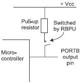
Figure 15.9 A pull-up circuit
PCL (program counter low)
PC is the program counter that keeps track of the instruction being executed at the time. It is a 13-bit register divided into PCL for low byte and PCH for high byte. Its behaviour is common with other microcontrollers and microprocessors as described in Chapter 8.
Stack
This register stores the return address when interrupts occur. It stores up to eight 13-bit addresses. Again, there are more details in Chapter 8.
Register 6–1: PIC16F84A configuration word
This is a special register which is just memory location 2007H which can only be accessed during programming. Unprogrammed pins are read as ‘1’.
It is a 13-bit word with the following options:
Bit 13–4. This protects the program code from being read after the programming is complete. 1 = no protection 0 = all program memory is code protected.
Bit 3 Power-up timer enabling. This allows a nominal 72 ms delay when first switching the microcontroller on to allow power supplies to settle. The delay can be activated by loading bit 3 with ‘0’, no delay = ‘1’.
Bit 2 watchdog timer, disable with ‘0’, enable with ‘1’.
Bits 1–0 oscillator selection bits
00 = LP oscillator
01 = HS oscillator
10 = XT oscillator
11 = RC oscillator
Oscillators
The crystal or ceramic resonator options are shown in Figure 15.10 and the crystal oscillators are divided into the frequency ranges:
LP low power crystals 32 kHz–200 kHz.
XT crystal/ceramic resonator 100 kHz–4 MHz.
HS high speed crystal/ceramic resonator 4 MHz–20 MHz.
RC resistor/capacitor.
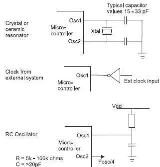
Figure 15.10 Oscillator options
A note on ceramic resonators
These offer an alternative to crystals for oscillators. They are generally lighter, more shock resistant and are usually somewhat smaller and cheaper to buy. The downside is that they do not have quite the frequency accuracy or stability and in many respects they are positioned somewhere between an RC network and the quartz crystal.
An interrupt summary
The PIC16F84A has four sources of interrupts:
(i) External interrupt on the RB0/INT pin.
(ii) TMR0 overflow.
(iii) PortB change detector pins RB7–RB4
(iv) EEPROM data write complete interrupt. This is used only when we are loading new programs into the EEPROM.
In each case, choose the best option.
1 An 8-bit microcontroller has:
(a) an 8-bit data bus.
Читать дальшеИнтервал:
Закладка:
Похожие книги на «Introduction to Microprocessors and Microcontrollers»
Представляем Вашему вниманию похожие книги на «Introduction to Microprocessors and Microcontrollers» списком для выбора. Мы отобрали схожую по названию и смыслу литературу в надежде предоставить читателям больше вариантов отыскать новые, интересные, ещё непрочитанные произведения.


Обсуждение, отзывы о книге «Introduction to Microprocessors and Microcontrollers» и просто собственные мнения читателей. Оставьте ваши комментарии, напишите, что Вы думаете о произведении, его смысле или главных героях. Укажите что конкретно понравилось, а что нет, и почему Вы так считаете.