John Crisp - Introduction to Microprocessors and Microcontrollers
Здесь есть возможность читать онлайн «John Crisp - Introduction to Microprocessors and Microcontrollers» весь текст электронной книги совершенно бесплатно (целиком полную версию без сокращений). В некоторых случаях можно слушать аудио, скачать через торрент в формате fb2 и присутствует краткое содержание. Год выпуска: 2004, ISBN: 2004, Издательство: Elsevier, Жанр: Компьютерное железо, на английском языке. Описание произведения, (предисловие) а так же отзывы посетителей доступны на портале библиотеки ЛибКат.
- Название:Introduction to Microprocessors and Microcontrollers
- Автор:
- Издательство:Elsevier
- Жанр:
- Год:2004
- ISBN:0-7506-5989-0
- Рейтинг книги:3 / 5. Голосов: 1
-
Избранное:Добавить в избранное
- Отзывы:
-
Ваша оценка:
Introduction to Microprocessors and Microcontrollers: краткое содержание, описание и аннотация
Предлагаем к чтению аннотацию, описание, краткое содержание или предисловие (зависит от того, что написал сам автор книги «Introduction to Microprocessors and Microcontrollers»). Если вы не нашли необходимую информацию о книге — напишите в комментариях, мы постараемся отыскать её.
Introduction to Microprocessors and Microcontrollers — читать онлайн бесплатно полную книгу (весь текст) целиком
Ниже представлен текст книги, разбитый по страницам. Система сохранения места последней прочитанной страницы, позволяет с удобством читать онлайн бесплатно книгу «Introduction to Microprocessors and Microcontrollers», без необходимости каждый раз заново искать на чём Вы остановились. Поставьте закладку, и сможете в любой момент перейти на страницу, на которой закончили чтение.
Интервал:
Закладка:
Mode 0
This is the case that spoils the simple RXD, TXD as, in this mode only, the TXD pin is actually used as a clock signal and the RXD is used to receive or transmit data. The clock frequency is fixed at 1/12 of the onboard oscillator frequency and this, of course, determines the speed at which the data is transferred via an 8-bit shift register.
Mode 1
This mode also sends data in 8-bit lumps but its frequency is adjustable and operates as an 8-bit UART (universal asynchronous receiver transmitter – see more about this in Chapter 17). The 8 bits are increased to 10 bits buy adding a logic 0 to indicate the start of the group and a logic 1 to mark the end of the group. This is the normal format used in RS232 transmissions. Unfortunately, the output voltages do not comply with the RS232 standards so an external chip must be added to do the voltage conversion. Some suitable chips are discussed in Chapter 17.
Mode 2
This is very similar to Mode 1 except the number of bits transmitted is increased from 10 bits to 11. The extra bit can be used as a parity bit which is used to check for transmission errors, The pattern is Start bit (0), 8 data bits, parity bit and stop bit (1). (Have a look at Chapter 17 again.) The transmission rate can be 1/32 or 1/64 of the onboard oscillator frequency.
Mode 3
This is an 11-bit transmission with a programmable baud rate. The baud rate is near enough the same as the transmission rate measured in bits per second.
Watchdog timer
When a microcontroller is embedded in equipment it may find itself used in areas where electrical interference is a problem. This, or a software problem can cause the microcontroller to lock up by getting into an endless loop. The watchdog timer will reset the microcontroller after a period of time, about 20 milliseconds, unless it is told not to. Stuck in a software loop, it no longer generates this ‘don’t reset me’ signal and so the microcontroller is reset and escapes from the loop.
The watchdog timer is only fitted into some of the 8051 variants but is available as a stand-alone chip but is commonplace in newer designs.
When we want to leave the microcontroller in a continuous loop, we have a choice of ensuring that the loop contains the required software code or disabling the watchdog timer before the loop is started.
Taking the AT90S/LS2343 as an example, we can see a really basic microcontroller with minimal complexity yet having many useful features that make it inexpensive, small and comparatively fast. The RISC design and the width of the registers allows the vast majority of instructions to be executed in a single clock cycle and all the others, apart from five, are completed in two cycles.
In Figure 15.5, we have a block diagram. It is quite a relief to see that mostly it is quite familiar after looking at the earlier 8-bit microprocessors and the 8051 considered in previous chapters. Already we see that most devices are a combination of one or two innovative ideas added to a standard mix.
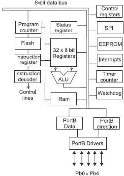
Figure 15.5 AVRAT90S/LS2343
Inputs and outputs
One notable feature of the block diagram, we see only five input/outputs shown as PortB 0 to 4 so we have only five connections for data which is a small number until we look at the sister version, the AT90S/LS2323 which has only three – PortB 0 to 2! Yet they are called 8-bit devices and in previous 8-bit micros we have grown to expect at least one and sometimes two 8-bit input/output connections. The answer is just that the ‘8-bit’ description refers to the internal data bus width.
The PortB pins can be used to send data in either direction, they can be used as inputs or outputs. As is common with other microprocessors and microcontrollers, the direction of data movement through each of the PortB lines is individually controlled by a data-direction register. Loading a ‘one’ into the data-direction register will make the corresponding PortB line into an output, on the other hand a ‘zero’, of course, will change it into an input.
Memories
This microcontroller has three memories, or four if we count the general purpose registers. The loading of the memory storage areas employs a serial transfer of data and is achieved by the SPI (serial programming interface).
One ROM storage area is achieved by a Flash memory organized as 1k×16. The program instructions are all either 16 or 32 bits wide and can be cleared and reprogrammed whilst remaining in circuit. It can be cleared and reprogrammed at least 1000 times. The contents of the Flash memory cannot be changed by the program being executed by the CPU and so is free from accidental corruption. The data is held in an EEPROM, which again can be cleared and reprogrammed electronically without removal from the device. It only holds 128 bytes of memory but is able to go through at least 100 000 cycles.
Data corruption can occur in the EEPROM if the supply voltage is reduced too far but this effect can be avoided by any one of the following three methods. The first we have already mentioned – use the Flash memory for critical data. The other two methods are ways to detect the reduction in voltage and immediately put the microcontroller into a safe condition. This is often referred to as ‘brown out protection’. An external circuit detects the falling voltage and applies a low voltage to the reset pin which effectively switches the chip off until the supply voltage recovers. The alternative is to put the microcontroller into a power-down sleep mode which is a power saving mode which has the effect of preventing any decoding or execution of any instructions – which, of course, precludes any ‘writes’ to the EEPROM.
It also has 128 bytes of SRAM (Static RAM) for the temporary storage of data and 32 8-bit general purpose registers that can be connected two at a time with the ALU (arithmetic and logic unit) which is the heart of the ‘brain’ within the microcontroller.
Clock
The AT90S/LS2343 has an internal RC oscillator which runs at 1 MHz, 4 MHz or 10 MHz depending on the version in use. It is one of the few of the micro devices that does not make use of an external crystal although it can use an external clock pulse. This external clock pulse only requires a single pin and hence we have an extra pin to use as an output.
Interrupts
There are only three interrupts. The first, and highest priority, is the reset which is activated by a low voltage applied to pin 1, a power-on reset or a signal from the watchdog. The next is an external interrupt request as described in a moment. Lastly, an overflow from the timer/counter circuit.
Pinout and package
These are shown in Figure 15.6 and we can see that it is available as an 8-pin DIL (dual in line) package which has two lines of pins and also the surface mount version, plastic gull wing SOIC (small outline IC).
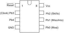
Figure 15.6 AT90S/LS2343 pinout
Pin 1 – Active low reset. Must go low for at least 50 ns.
Pin 2 – External clock signal input or PortB 3
Pin 3 – PortB 4. All lines can sink 20 mA and therefore are able to power LEDs directly. Sinking means that the LED or other load is connected between the positive Vcc supply and a low voltage output at the port.
Pin 4 – Ground.
Pin 5 – PortB 0 or MOSI. In serial programming mode, MOSI is the serial data input.
Читать дальшеИнтервал:
Закладка:
Похожие книги на «Introduction to Microprocessors and Microcontrollers»
Представляем Вашему вниманию похожие книги на «Introduction to Microprocessors and Microcontrollers» списком для выбора. Мы отобрали схожую по названию и смыслу литературу в надежде предоставить читателям больше вариантов отыскать новые, интересные, ещё непрочитанные произведения.


Обсуждение, отзывы о книге «Introduction to Microprocessors and Microcontrollers» и просто собственные мнения читателей. Оставьте ваши комментарии, напишите, что Вы думаете о произведении, его смысле или главных героях. Укажите что конкретно понравилось, а что нет, и почему Вы так считаете.