John Crisp - Introduction to Microprocessors and Microcontrollers
Здесь есть возможность читать онлайн «John Crisp - Introduction to Microprocessors and Microcontrollers» весь текст электронной книги совершенно бесплатно (целиком полную версию без сокращений). В некоторых случаях можно слушать аудио, скачать через торрент в формате fb2 и присутствует краткое содержание. Год выпуска: 2004, ISBN: 2004, Издательство: Elsevier, Жанр: Компьютерное железо, на английском языке. Описание произведения, (предисловие) а так же отзывы посетителей доступны на портале библиотеки ЛибКат.
- Название:Introduction to Microprocessors and Microcontrollers
- Автор:
- Издательство:Elsevier
- Жанр:
- Год:2004
- ISBN:0-7506-5989-0
- Рейтинг книги:3 / 5. Голосов: 1
-
Избранное:Добавить в избранное
- Отзывы:
-
Ваша оценка:
Introduction to Microprocessors and Microcontrollers: краткое содержание, описание и аннотация
Предлагаем к чтению аннотацию, описание, краткое содержание или предисловие (зависит от того, что написал сам автор книги «Introduction to Microprocessors and Microcontrollers»). Если вы не нашли необходимую информацию о книге — напишите в комментариях, мы постараемся отыскать её.
Introduction to Microprocessors and Microcontrollers — читать онлайн бесплатно полную книгу (весь текст) целиком
Ниже представлен текст книги, разбитый по страницам. Система сохранения места последней прочитанной страницы, позволяет с удобством читать онлайн бесплатно книгу «Introduction to Microprocessors and Microcontrollers», без необходимости каждый раз заново искать на чём Вы остановились. Поставьте закладку, и сможете в любой момент перейти на страницу, на которой закончили чтение.
Интервал:
Закладка:
Pin 6 – PortB 1 or MISO/INT0. In serial programming mode, MISO is the serial data output. This pin can also act as the external interrupt described in the previous paragraph.
Pin 7 – PortB 2 or SCK/T0. In serial programming mode, SCK is the serial clock input. This pin can also provide the timer/counter0 clock input.
Pin 8 – Vcc. The LS version requires a positive supply voltage that remains in the range 2.7–6.0 V.
Sleep modes
When the microcontroller is not being used, it can switch off some of its circuitry to save power. Sleep modes are employed in all modern microcontrollers and make an enormous difference to the overall life of an intermittently used device. This enables sealed units in toys and greetings cards to remain active for months or years.
Idle-mode
To see the benefits, this microcontroller has a normal operating current drain of 2.4 mA but when switched to the ‘idle’ mode, the current falls to 0.5 mA. It does this by stopping the CPU activity but allows the timer/counter, watchdog and interrupts to remain operational. This is about an 80% power reduction but we can do a lot better than that otherwise my musical socks would have stopped long ago.
Power-down mode
In this mode, only the external interrupt and watchdog (if enabled) continue to work and current falls to less than 1 microamp, which is a really impressive reduction in power. The microcontroller can be aroused from its sleep only by one of the following: an external reset, the watchdog (if enabled) or INTO external interrupt.
This is another modern RISC development and has many features that are similar to the AVR that we have just looked at. The AT90S/LS2343 was chosen as representative of the very small and basic microcontrollers found embedded in many products. This PIC16F84A example from Microchip Technology is a mid-range device which is larger and more capable than the AVR.
The PIC series ranges from a really simple 8-pin, 4 MHz microcontroller on a level with the AT90S/LS2343 that we have just considered up to a 40-pin 25 MHz device. As mentioned the PIC16F84A is a mid-size version that has 18 pins and runs up to 20 MHz.
The PICs are designed for easy use and are becoming increasingly popular as the first step into the world of microcontrollers. Microchip Technology provides a PICSTART™ PIC development system that provides, at a very reasonable price, an assembler, compiler, EPROM and EEPROM programmer, all the hardware manuals and even a sample PIC to play with. It should be mentioned that other companies have similar systems compatible with the PIC series and for other microcontrollers like the AVR and 8051 series.
It has proved to be such an easy, off the shelf, starting point that to many people ‘PIC’ is not only their first choice but is becoming used as a generic term for any microcontroller.
The general layout of the PIC16F84A is shown in Figure 15.7.
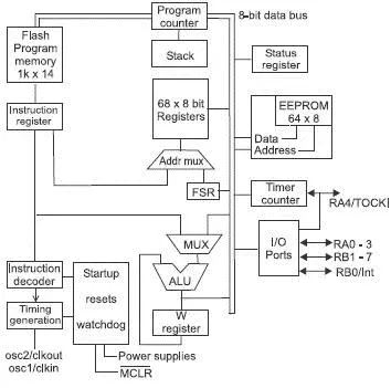
Figure 15.7 PIC16F84A
Supply voltage
The DC supply voltage must remain in the range 2.0–5.5 V for it to work happily though similar versions such as the PIC16F84 can run between 2.0 and 6.0 V.
Sleep mode
To save the current drain, a software instruction can put the PIC into a sleep mode. The supply current is very dependent on the clock frequency and is normally between 1 and 20 mA and when put to sleep the drain is reduced to approximately 1 µA. To obtain the lowest possible sleep current we should hold all I/O pins at VDD or VSS and disable any external clock and hold the master clear pin in a logic high state – not in the reset state. The purpose of all this is to prevent any voltages from floating up and down. If it did so, it would switch and the technology used results in very low currents drawn except at the moment of switching during which it causes a really high spike of current so the higher the frequency, the more often this spike occurs – hence the increased current.
The microprocessor will wake if: a reset occurs by a logic low voltage being applied to the MCLR pin, a wakeup pulse arrives from the watchdog unit (if it is enabled) or an ‘EEPROM write complete’ signal.
Memory
As usual, we have two blocks of memory. One is the program memory and the other is for data. For maximum speed, they each have a separate bus connection so that both memories can be accessed during a single clock cycle.
Program memory
The program memory is situated in the flash memory which is organized as 1028×14. All instructions in the PIC16 series use 14-bit instructions.
The reset vector points to address 0000H and the interrupt vector is 0004H so address locations 0005H to 03FFH are available for us to hold our programs.
Data memory
The data area is subdivided into two areas, the FSR (file select register) and the GP (general purpose registers) as shown in Figure 15.8.
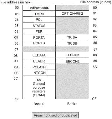
Figure 15.8 Register file map
The SFR (special function register)
This register controls the operation of the CPU and involves such things as the input and output ports, EEPROM address and data, timer, program counter and that sort of housekeeping.
All the register files are 8-bits wide and are arranged in two banks called bank 0 and bank 1. We have to instruct the microcontroller as to which bank is to be used and this is done by using special instructions to access some of the page 1 registers. Those accessible are indicated in Figure 15.8. Microchip Technology are planning to remove the choice of using the OPTION and the two TRIS registers and suggest that the STATUS register is used instead. This does not affect the use with this chip but it will ensure that upgrading in the future will not require any modifications to the software.
I/O (input/output) ports
All outputs can source or sink 25 mA and can therefore power significant external circuits without further power amplifiers being required. Sinking means that the load is connected between the positive Vcc supply and a low voltage output at the port and sourcing is connecting the load between a positive output on the pin to the ground.
PortA and TRISA registers
PortA is a 5-bit wide bi-directional port, each line being individually controlled so some of the lines can be inputs whilst the others are outputs. The choice of input or output is made by loading a 0 (output) or a 1 (input) into the appropriate bit of the data direction register TRISA.
In common with other devices, when it first starts at power-on, the port is set as an input. This provides a safer option that running the risk of random information being sent out to whatever it is connected to.
PortB and TRISB registers
PortB is a 8-bit wide bi-directional port, each line being individually controlled using TRISB in the same manner as in PortA. Each of the PortB pins have a weak internal pull-up which can be switched on or off by the RBPU of the option register. The pull-ups are disabled when the port is being used as an output and also during power switchon. Any of the Pins RB4–RB7 that just happen to be configured as an input have an interrupt-on-change feature that can be useful. If any one or more of these pins have changed logic state since they were last read, it causes an RB port change interrupt. This interrupt can be used to wake the microcontroller from its ‘sleep’ mode.
Читать дальшеИнтервал:
Закладка:
Похожие книги на «Introduction to Microprocessors and Microcontrollers»
Представляем Вашему вниманию похожие книги на «Introduction to Microprocessors and Microcontrollers» списком для выбора. Мы отобрали схожую по названию и смыслу литературу в надежде предоставить читателям больше вариантов отыскать новые, интересные, ещё непрочитанные произведения.


Обсуждение, отзывы о книге «Introduction to Microprocessors and Microcontrollers» и просто собственные мнения читателей. Оставьте ваши комментарии, напишите, что Вы думаете о произведении, его смысле или главных героях. Укажите что конкретно понравилось, а что нет, и почему Вы так считаете.