John Crisp - Introduction to Microprocessors and Microcontrollers
Здесь есть возможность читать онлайн «John Crisp - Introduction to Microprocessors and Microcontrollers» весь текст электронной книги совершенно бесплатно (целиком полную версию без сокращений). В некоторых случаях можно слушать аудио, скачать через торрент в формате fb2 и присутствует краткое содержание. Год выпуска: 2004, ISBN: 2004, Издательство: Elsevier, Жанр: Компьютерное железо, на английском языке. Описание произведения, (предисловие) а так же отзывы посетителей доступны на портале библиотеки ЛибКат.
- Название:Introduction to Microprocessors and Microcontrollers
- Автор:
- Издательство:Elsevier
- Жанр:
- Год:2004
- ISBN:0-7506-5989-0
- Рейтинг книги:3 / 5. Голосов: 1
-
Избранное:Добавить в избранное
- Отзывы:
-
Ваша оценка:
Introduction to Microprocessors and Microcontrollers: краткое содержание, описание и аннотация
Предлагаем к чтению аннотацию, описание, краткое содержание или предисловие (зависит от того, что написал сам автор книги «Introduction to Microprocessors and Microcontrollers»). Если вы не нашли необходимую информацию о книге — напишите в комментариях, мы постараемся отыскать её.
Introduction to Microprocessors and Microcontrollers — читать онлайн бесплатно полную книгу (весь текст) целиком
Ниже представлен текст книги, разбитый по страницам. Система сохранения места последней прочитанной страницы, позволяет с удобством читать онлайн бесплатно книгу «Introduction to Microprocessors and Microcontrollers», без необходимости каждый раз заново искать на чём Вы остановились. Поставьте закладку, и сможете в любой момент перейти на страницу, на которой закончили чтение.
Интервал:
Закладка:
The family is given a name which often has little connection with the product codes. For example, Intel’s 8051 family has the family name of MCS51. This contains the 803X, 805X, 875X and the low power versions bXC45X and the 8XCX52. As usual the X refers to any figure or letter in that position.
The situation is further confused (or possibly simplified) by referring to all of them as ‘the’ 8051.
The block diagram of the 8051
The block diagram shown in Figure 15.1 is the family portrait of the 8051 family. There are some features that differ between the family members, principally the memory configuration – some versions have less memory and some have none at all. However, we will look at the operation of our ‘middle-of-the-road’ version and worry about the individual differences later.
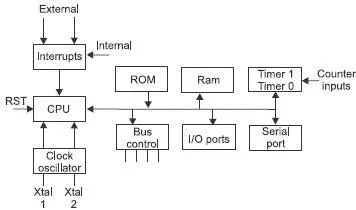
Figure 15.1 8051 block diagram
The 8051 pinout
As in all micro and digital chips, a line over a pin designation indicates that it is active low or, put more simply, to use this feature we need to apply zero volts.
The pinout shown in Figure 15.2 looks, at first glance to be rather complicated due to the dual use of many pins. This is a common feature of microcontrollers as a method of reducing the number of pins to be used. The more pins, the more expensive and the larger the device. This is bad news for a device often destined to be embedded within another circuit.
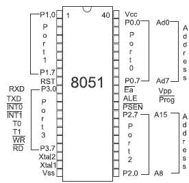
Figure 15.2 Pinout of the 8051
There are variants available that provide the increased number of pins so that there is a separate pin for each function.
Reset
Regardless of what program is being run, we must always be able to gain control of the microcontroller just as we must with a microprocessor. The procedure is just the same. The microcontroller has a reset pin which, in the 8051, is taken from the bus control block and, in normal operation must be held to zero volts. When a positive voltage over 2.0 V is applied to it the microcontroller immediately returns to its startup memory location, which in this case is 0000H. We can arrange this to occur automatically when the power is switched on but we should also provide a reset switch to gain control of the system at any time without removing the power. This is the ‘reset’ switch which we use when our computer locks up and ignores us.
When changing microcontrollers, remember to check the polarity of the reset voltage. Compare this circuit in Figure 15.3 with the one shown in Figure 8.7.
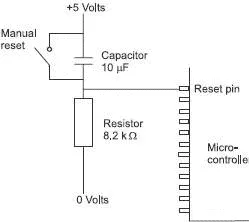
Figure 15.3 The reset switch
Clock input
As we have seen in Chapter 7, we are going to need a clock signal. The original design of the 8051 called for a 12 MHz crystal though later versions can run at 33 MHz, 40 MHz or even 44 MHz. As an alternative, we can use a ceramic resonator or an external signal. The clock input is shown in Figure 15.4 using a crystal. To use an external signal throw away the crystal and the capacitors then apply the external signal to the Xtal1 pin and leave Xtal2 disconnected.
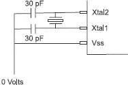
Figure 15.4 The clock
Ports
We have four ports numbered 0 to 3. In the standard 8051 ports 0, 2 and 3 are dual purpose and port 1 is just an input/output port. In some variants, all ports are dual purpose.
With regard to the memory, we can use the on-chip memory, which keeps the circuit as simple as possible and makes the embedding of the device at its most convenient.
The on-chip memory may be masked ROM or an EPROM which we met in Chapter 6. To use external memory obviously increases the chip count but can allow up to 64 kB of memory, which is the standard size for 8-bit microprocessors.
The external memory is accessed by taking the ‘external access’ (EA) pin to a logic zero. To switch the external ROM on, the output enable (OE) pin of the external memory is taken low by the program store enable (PSEN) pin of the 8051. In a similar way, an external RAM is accessed for reading and writing by the read (RD) and write (WR) pins applying a logic zero voltage to the output enable (OE) and read/write (R/W) pins respectively.
Interrupts
The 8051 has a total of five interrupt signals. Two of these can be externally generated and three are of internal origin. Interrupts are discussed more generally in the chapter dealing with interfacing but basically, when an interrupt occurs, the program which is running at the time is interrupted and another code sequence is ran, called an interrupt service routine (ISR). When the ISR is compete, the microcontroller returns to its original program and continues as if the interruption has not occurred. There is a different ISR for each interrupt which must be pre-loaded in specific memory addresses, all ready to go if needed.
What if two interrupts occur at the same time?
The interrupts are checked continuously in what we call the polling order. Starting from the top, the order in the 8051 is:
External Interrupt 0
Timer 0
External Interrupt 1
Timer 1
Serial port
In addition, each interrupt can be given two levels of priority so if two interrupts occur, the one with the high priority will be handled first. If two have the same priority, it is decided by the polling order.
Timer/counters
A timer or counter is a series of bistables or flip-flops that change state once for every input signal, thus one of these circuits would divide the input frequency by a factor of two. If this signal is then fed into the next bistable, the output is ¼ of the original frequency. The next circuit would have an output of 1/8, then 1/16 and so on.
There are two timers, T0 and T1. These can be programmed to divide by 256, 8192 or 65536 and will generate an interrupt signal upon completion that can be detected by the software. One of the modes allows the timer/counter in 8-bit (divide by 256) mode to reload and start counting again each time continuously.
The input signal being counted can originate from an external circuit so it counts the number of incoming pulses, or it can use an internal signal which is actually 1/12 of the clock frequency in use. As mentioned above, it generates an interrupt signal when it reaches its maximum value. We can preload the timer with a number to start counting from. This will allow the interrupt to be generated after any required number of events, or time interval.
Serial port
Since the microcontroller normally handles data eight bits at a time, it is operating in parallel but two receive or transmit serial data we have perform serial/parallel conversions. This is always achieved by using a shift register working under the control of a clock signal. The working of a shift register is described in Chapter 17.
The serial port is able to transmit and receive data, at the same time, this is referred to as a full duplex system. As the name suggests, the bits of data are moved one after the other in a continuous stream. Pin 10 is called RXD or receive data and pin 11 is the TXD, transmit data but, as is often the case, things are not quite that simple.
It can operate in three ways, or modes numbered 0, 1, 2 and 3.
Читать дальшеИнтервал:
Закладка:
Похожие книги на «Introduction to Microprocessors and Microcontrollers»
Представляем Вашему вниманию похожие книги на «Introduction to Microprocessors and Microcontrollers» списком для выбора. Мы отобрали схожую по названию и смыслу литературу в надежде предоставить читателям больше вариантов отыскать новые, интересные, ещё непрочитанные произведения.


Обсуждение, отзывы о книге «Introduction to Microprocessors and Microcontrollers» и просто собственные мнения читателей. Оставьте ваши комментарии, напишите, что Вы думаете о произведении, его смысле или главных героях. Укажите что конкретно понравилось, а что нет, и почему Вы так считаете.