John Crisp - Introduction to Microprocessors and Microcontrollers
Здесь есть возможность читать онлайн «John Crisp - Introduction to Microprocessors and Microcontrollers» весь текст электронной книги совершенно бесплатно (целиком полную версию без сокращений). В некоторых случаях можно слушать аудио, скачать через торрент в формате fb2 и присутствует краткое содержание. Год выпуска: 2004, ISBN: 2004, Издательство: Elsevier, Жанр: Компьютерное железо, на английском языке. Описание произведения, (предисловие) а так же отзывы посетителей доступны на портале библиотеки ЛибКат.
- Название:Introduction to Microprocessors and Microcontrollers
- Автор:
- Издательство:Elsevier
- Жанр:
- Год:2004
- ISBN:0-7506-5989-0
- Рейтинг книги:3 / 5. Голосов: 1
-
Избранное:Добавить в избранное
- Отзывы:
-
Ваша оценка:
Introduction to Microprocessors and Microcontrollers: краткое содержание, описание и аннотация
Предлагаем к чтению аннотацию, описание, краткое содержание или предисловие (зависит от того, что написал сам автор книги «Introduction to Microprocessors and Microcontrollers»). Если вы не нашли необходимую информацию о книге — напишите в комментариях, мы постараемся отыскать её.
Introduction to Microprocessors and Microcontrollers — читать онлайн бесплатно полную книгу (весь текст) целиком
Ниже представлен текст книги, разбитый по страницам. Система сохранения места последней прочитанной страницы, позволяет с удобством читать онлайн бесплатно книгу «Introduction to Microprocessors and Microcontrollers», без необходимости каждый раз заново искать на чём Вы остановились. Поставьте закладку, и сможете в любой момент перейти на страницу, на которой закончили чтение.
Интервал:
Закладка:
(b) eight ports.
(c) an 8-bit address bus.
(d) eight internal registers.
2 Compared with the Pentium 4, a microcontroller:
(a) is faster.
(b) consumes less current.
(c) is more complex.
(d) is larger.
3 watchdog circuit prevents:
(a) damage due to excessively high supply voltages.
(b) an overrun in timer/counter circuits.
(c) burglars.
(d) wastage of power while the microcontroller is not being used.
4 It is NOT essential for a microcontroller circuit to include:
(a) registers.
(b) a reset pin.
(c) some memory.
(d) a crystal.
5 The term ‘ISR’ refers to an:
(a) immediate service register.
(b) internal system reset.
(c) interrupt service routine.
(d) instruction set register.
16. Using a PIC microcontroller for a real project
PIC microcontrollers are a very convenient choice to get started in this field although, as we have seen, there are enormous areas of overlap between microprocessors and other microcontroller designs.
One convenience is that Microchip Technology has taken the RISC concept seriously. There are only 35 instructions and, of these, only a few are required to write quite usable programs.
All data movements are based around just a single register called ‘W’ for ‘working’. This performs much the same function as the accumulator in the earlier processors like the 6502.
To program the PIC we need a copy of software instructions and more details of the register layout.
There is no getting away from the fact that when we first meet a microcontroller, the information appears overwhelming – not only in the quantity but in the apparent complexity. This is despite the efforts of the designers to make it as simple as possible. It is very much like seeing a new foreign language, which it is really – and tackle it in much the same way, a bit at a time.
There are four golden rules which may help:
1 Don’t get scared! From time to time, it will seem tempting just to throw it all away and find something easier to do.
2 Start really simple – one step at a time.
3 Be prepared for it to take a long time in the early stages.
4 When you are feeling low and despondent, remember that everyone else has felt the same. It will get better. Honest.
Let’s keep it really simple. We have to buy a microcontroller and connect it up and then program it.
The device that we are going to use is a PIC16F84A-04/P. The pinout is shown in Figure 16.1. The number PIC16F84A is the type of microcontroller. The 04 tells us that the maximum frequency is 4 MHz and the /P means that it is the standard plastic package. There is no minimum operating frequency and the slower it runs, the less power it consumes.

Figure 16.1
Figure 16.2 shows the most basic circuit. It includes only the chip supplies and a positive supply to prevent the MCLR (master clear) from for a real project accidentally resetting the PIC during the program. Unless they are tied to a definite value all disconnected inputs will float up and down and can cause random switching.
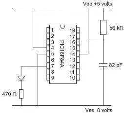
Figure 16.2
We need a clock signal and the simplest and cheapest is just an RC combination. The resistor should be between 5 kΩ and 100 kΩ and the capacitor should be greater than 20 pF. The values chosen for this circuit were not selected carefully and are not critical. In practice, it is difficult to predict the operating frequency of an RC combination. If we need a particular frequency it is better to use a variable resistor and adjust it to give the desired frequency.
Later on, when we have written the program we must tell the assembler what clock signal we are going to use. This programs the PIC to expect an RC oscillator. This information can, as an alternative, be included into the program. It’s our choice but it is slightly easier to do it at the assembly stage but we must remember to do it.
There are three layers of information that we need to use the registers. Firstly, we need the names and addresses of the files as we met in the register file map in Figure 15.8. The second step is the function of each bit in each register, and this is shown in Appendix A, and finally, an explanation of these functions as we see in Appendix B.
All this data looks daunting but the thing to remember is that we only use one bit at a time and we can ignore the rest.
All PICs and indeed all microprocessors and microcontrollers use binary code and nothing else. To make life easier for us, we use assembly language or a high level language. To use these languages, we need a program which is able to convert them to binary code. For assembly language, the required program is called an assembler and for higher level languages a similar job is done by a compiler.
An assembler is part of the PICSTART PLUS development system but there are other assemblers available that will handle code for all the PICs. The code that we write as the input to the assembler is called ‘source code’ and the code that is supplied by the assembler is called ‘object code’. The object code is really in binary but to make it easier for us, it is usually displayed on the screen in hex.
Important note
As we type in the program we must not leave any spaces in instructions or in the data.
The purpose of our first program
We want to do something really simple but not something that may have happened by accident. We are going to configure all of PortB as outputs and then make the output signal to be off, on, off, on, off, on, off, on. We can connect a series of LEDs to the output pins so alternate lights will be on.
1 We will start by selecting Bank 1 of the register file map. To do this we need to talk to the status register, so by referring to Figure 15.8, we can see that the status register is file 03. From our look at the Status register in Chapter 15, we can see that bit 5 is the RP0 which controls the selection of Bank0 or Bank1. The first line of the program must set bit 5 of register 3.
Program starts:
BSF 3,5; Sets bit 5 of register 3 to select Bank1
It is worth mentioning at this stage, that anything written after the semicolon is just a note for us and is ignored by the assembly program. This is called the comment field. It is always worth using this area to explain the program, and this often saves hours trying to remember what we were attempting to do when we first wrote the program. This can be an even larger problem if someone else writes a program and is then off sick and we are left to find out why the program doesn’t work.
2 We now want to arrange for PortB to be an output. This involves loading a 0 into each of the controlling bits in the data direction register which we can see from Figure 15.8 is called TRISB and is register number 86. To do this, we are going to clear the W register using the CLRW instruction and then copy this zero into register 86. This involves two extra instructions so, at this stage, our program will read:
BSF 3,5 ; Sets bit 5 of register 3 to select Bank1
CLRW ; puts a zero into register W
MOVWF 86; copies the zero into register 86 which is
Интервал:
Закладка:
Похожие книги на «Introduction to Microprocessors and Microcontrollers»
Представляем Вашему вниманию похожие книги на «Introduction to Microprocessors and Microcontrollers» списком для выбора. Мы отобрали схожую по названию и смыслу литературу в надежде предоставить читателям больше вариантов отыскать новые, интересные, ещё непрочитанные произведения.


Обсуждение, отзывы о книге «Introduction to Microprocessors and Microcontrollers» и просто собственные мнения читателей. Оставьте ваши комментарии, напишите, что Вы думаете о произведении, его смысле или главных героях. Укажите что конкретно понравилось, а что нет, и почему Вы так считаете.