John Crisp - Introduction to Microprocessors and Microcontrollers
Здесь есть возможность читать онлайн «John Crisp - Introduction to Microprocessors and Microcontrollers» весь текст электронной книги совершенно бесплатно (целиком полную версию без сокращений). В некоторых случаях можно слушать аудио, скачать через торрент в формате fb2 и присутствует краткое содержание. Год выпуска: 2004, ISBN: 2004, Издательство: Elsevier, Жанр: Компьютерное железо, на английском языке. Описание произведения, (предисловие) а так же отзывы посетителей доступны на портале библиотеки ЛибКат.
- Название:Introduction to Microprocessors and Microcontrollers
- Автор:
- Издательство:Elsevier
- Жанр:
- Год:2004
- ISBN:0-7506-5989-0
- Рейтинг книги:3 / 5. Голосов: 1
-
Избранное:Добавить в избранное
- Отзывы:
-
Ваша оценка:
Introduction to Microprocessors and Microcontrollers: краткое содержание, описание и аннотация
Предлагаем к чтению аннотацию, описание, краткое содержание или предисловие (зависит от того, что написал сам автор книги «Introduction to Microprocessors and Microcontrollers»). Если вы не нашли необходимую информацию о книге — напишите в комментариях, мы постараемся отыскать её.
Introduction to Microprocessors and Microcontrollers — читать онлайн бесплатно полную книгу (весь текст) целиком
Ниже представлен текст книги, разбитый по страницам. Система сохранения места последней прочитанной страницы, позволяет с удобством читать онлайн бесплатно книгу «Introduction to Microprocessors and Microcontrollers», без необходимости каждый раз заново искать на чём Вы остановились. Поставьте закладку, и сможете в любой момент перейти на страницу, на которой закончили чтение.
Интервал:
Закладка:
; select Bank1
CLRW ; puts a zero into register
; W
MOVWF PortBDDR; copies the zero into
; register 86 which is the
; PortB data direction
; register
BCF Status,RP0; clears bit 5 of register 3
MOVLW Data ; output data to give the
; on, off sequence
again MOVWF PortB ; this copies the data into
; PortB
GOTO again ; this line forces the micro
; to return to the previous
; line
END ; the end of our code to be
; assembled
By making full use of labels, we have rewritten our program without any numbers at all. This is just a matter of choice – all labels, some labels or no labels, whatever we like.
This gives a more accurate clock speed so that programs that involve real can be written. It may be that we want a display sequence to run at a particular rate.
To change to a crystal we need to set up the configuration bits in the PIC so that it knows that it is being controlled by a crystal instead of the RC method. This is most easily handled during the assembly process by clicking on ‘configuration bits’ and selecting the clock source from the options offered.
The two capacitors shown in Figure 16.3 in the clock circuit always have equal values and the range shown is suitable for 200 kHz and all clocks of 2 MHz and over. Other recommended values are: 32 kHz — 68/100 pF and 100 kHz — 100/150 pF. The higher values in each range results in higher stability but slower startup times.
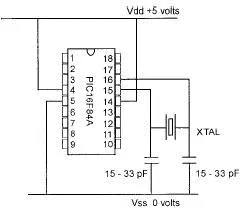
Figure 16.3 A Crystal Controlled Clock
A ceramic resonator can be used as a plug-in replacement for the crystal.
In the last program we controlled the voltages to each of the PortB outputs. With slight modifications we would be able to apply any combinations of voltages to control any external circuits. Even this first circuit has significant control capabilities but now we are going to extend the capability by applying a counting sequence to the output signals.
All programs are built on the backs of other programs that we have used before so we can save considerable time by keeping copies of our successful programs to be recycled whenever possible. This is well demonstrated in this example.
The program consists of three steps, two of which we have already designed and tested, so we know it works. If the new program refuses to work, we don’t have to start from scratch, we know two–thirds of it is OK. This is a very powerful method of designing programs and whole libraries of programs are available so new developments can be reduced to slotting together ready-made program segments.
When we make changes to a previously program, it is important to save the new version under a new name so that, in the event of a disaster, we can retreat and start again.
Here is the section that we have ‘borrowed’ from our previous work:
ORG 000
BSF 3,5
CLRW
MOVWF 86; PortB data direction = output
BCF 3,5
MOVLW 55
MOVWF 06; PortB data set to a start value
At this stage we can, of course, set the start value for the output to any value between 00H to FFH which is binary B’00000000’ to B’11111111’.
We have only one new instruction to worry about: INCF f,d. It increments or increases the value of a selected file ‘f’ by 1, and where the new value goes to is determined by the value of the ‘d’ term. If ‘d’ is 0 the new value is put into the W register but if it is 1, the new value is put back into the register in use.
PortB data register is register 06 so the code INCF 06,1 will take the current value of PortB data, increase it by 1 and put the answer back into PortB data so our starting value of 55 will change to 56 and the output voltages on the pins will change from 01010101 to 01010110.
This was just a single count, but for a continuous count we could use a label to make the program jump back and do the INCF trick again and again. When it reaches its maximum value, it will roll over to zero and start again so the count process can be continuous. Our program would now be:
ORG 000
BSF 3,5
CLRW
MOVWF 86 ; PortB data direction = output
BCF 3,5
MOVLW 55
MOVWF 06 ; PortB data set to a start value
again INCF 06,1
goto again; go back and INCF again
end ; end of source code
One more step
The speed at which the count continues is determined by the rate at which instructions are being followed.
Slowing things down
If we wish to slow things down, we can give the microcontroller something to do just to keep it busy. We have a NOP instruction which does absolutely nothing but takes one instruction cycle to do it. Since it doesn’t do anything, it doesn’t matter how many we include in a program, or where we use them. For a significant delay we made need hundreds, which is not an elegant way of solving a problem.
In the last modification to the problem, we made it count up on the PortB register. Now this takes time, so we could use this counting trick as a time waster. The PIC has 68 general purpose registers that can be made to count for us. Just choose any one of them and have it count for a set number of counts and then we can go back and count once on the PortB register, then go back to the time waste count. In Figure 16.4, we have loaded a register with a number, say 30H (48 in decimal). The next instruction decreases it by 1 to give 2FH (not 29!!!) and since the answer is not zero, we go around the loop and decrement it again to 2EH and so on until it gets to zero whereupon it leaves the loop to carry out ‘instruction 2’ shown in the figure.
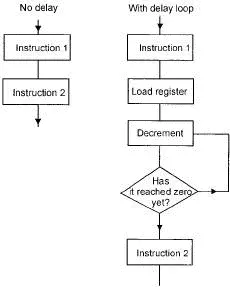
Figure 16.4 Using a timing loop
The instruction we are going to use this time is INCFSZ f,d. This is designed just for this type of counting job. It decrements the chosen register and if d=0, the result goes into the W register but if it is 1, it will go back into the same register. For our purposes we would load the code as DECFSZ 20,1. This would decrement register 20 and put the answer back into register 20. When this register reaches zero, it will miss out the next instruction to stop it going around the loop again and will move on to the next instruction.
A slower count
Once again, this uses some of our previous programs.
ORG 000
BSF 3,5
CLRW
MOVWF 86 ; PortB data direction = output
BCF 3,5
MOVLW 55 ; PortB data set to a start value
MOVWF 06
again INCF 06,1
MOVLW 30 ; Loads W with 30H
MOVWF 20 ; puts the number 30 into file 20
count DECFSZ 20,1; decrements register 20
goto count ; keeps decrements until it gets to zero
goto again ; returns to increment PortB
end
For the slowest count on PortB, we would have to increase the count number in register 20 to its maximum number which, using this microcontroller is 7FH or 127 in decimal.
Читать дальшеИнтервал:
Закладка:
Похожие книги на «Introduction to Microprocessors and Microcontrollers»
Представляем Вашему вниманию похожие книги на «Introduction to Microprocessors and Microcontrollers» списком для выбора. Мы отобрали схожую по названию и смыслу литературу в надежде предоставить читателям больше вариантов отыскать новые, интересные, ещё непрочитанные произведения.


Обсуждение, отзывы о книге «Introduction to Microprocessors and Microcontrollers» и просто собственные мнения читателей. Оставьте ваши комментарии, напишите, что Вы думаете о произведении, его смысле или главных героях. Укажите что конкретно понравилось, а что нет, и почему Вы так считаете.