John Crisp - Introduction to Microprocessors and Microcontrollers
Здесь есть возможность читать онлайн «John Crisp - Introduction to Microprocessors and Microcontrollers» весь текст электронной книги совершенно бесплатно (целиком полную версию без сокращений). В некоторых случаях можно слушать аудио, скачать через торрент в формате fb2 и присутствует краткое содержание. Год выпуска: 2004, ISBN: 2004, Издательство: Elsevier, Жанр: Компьютерное железо, на английском языке. Описание произведения, (предисловие) а так же отзывы посетителей доступны на портале библиотеки ЛибКат.
- Название:Introduction to Microprocessors and Microcontrollers
- Автор:
- Издательство:Elsevier
- Жанр:
- Год:2004
- ISBN:0-7506-5989-0
- Рейтинг книги:3 / 5. Голосов: 1
-
Избранное:Добавить в избранное
- Отзывы:
-
Ваша оценка:
Introduction to Microprocessors and Microcontrollers: краткое содержание, описание и аннотация
Предлагаем к чтению аннотацию, описание, краткое содержание или предисловие (зависит от того, что написал сам автор книги «Introduction to Microprocessors and Microcontrollers»). Если вы не нашли необходимую информацию о книге — напишите в комментариях, мы постараемся отыскать её.
Introduction to Microprocessors and Microcontrollers — читать онлайн бесплатно полную книгу (весь текст) целиком
Ниже представлен текст книги, разбитый по страницам. Система сохранения места последней прочитанной страницы, позволяет с удобством читать онлайн бесплатно книгу «Introduction to Microprocessors and Microcontrollers», без необходимости каждый раз заново искать на чём Вы остановились. Поставьте закладку, и сможете в любой момент перейти на страницу, на которой закончили чтение.
Интервал:
Закладка:
The likely options are as follows
There are two basic types of hardware interrupt. The first is an interrupt request or IRQ (or INTR) pin. This tells the microprocessor that it would like to have some attention. Since it is a request rather than an order, the microprocessor is free to say ‘yes’ or ‘no’ or ‘yes, but not at the moment – just wait till I’m ready’. This does not imply any intelligence on the part of the microprocessor – it must be told which response to give by the software that is being run at the time. In the absence of any instruction, it normally accepts the interruption. If a particular interrupt pin has been told not to respond to an interrupt, we say that the interrupt has been ‘masked’.
The second type is called a non-maskable interrupt, that is, an unstoppable demand for attention. This will always assume top-priority. A typical use for this would be for an emergency shutdown in the event of a power failure. The program can also instigate an interrupt by means of a software instruction as part of a program.
What is a hardware interrupt signal?
This is a change of voltage on an interrupt pin generated by the external device. The change required would be detailed in the technical data but there are four choices.
The first two choices are changes of voltage level. The pin can sit at +3.3 V or whatever the ‘high’ voltage happens to be, then responds when it falls to 0 V. We call this ‘active low’. When the pin goes low, an interrupt is recognized. Alternatively, it could sit at 0 V and become activated by an increased voltage. This we call ‘active high’.
The alternative approach is to use the sudden change of level. From low to high is called ‘leading edge’ or ‘rising edge’ and from high to low is the ‘trailing edge’ or ‘falling edge’ (See Figure 17.1 and have a glance at Figure 6.4 to see the alternative names.)
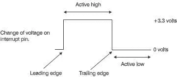
Figure 17.1 Four ways of signalling an interrupt
Once an interrupt is activated, the signal must be returned to its normal voltage before it can be triggered again. The input is masked as the interrupt program is running to prevent the interrupt pin from interrupting itself if the voltage remains at its active level.
Accommodating several external devices
The simplest and quickest way of connecting devices to the interrupts of a microprocessor is to have each device connected to its own interrupt pin. This is OK providing there are enough pins. Few microprocessors have more than two interrupt pins so we have to connect several devices to the same pin.
When an interrupt occurs, a program called the ‘first level interrupt handler’ or FLIH is activated. The function of the FLIH is to identify the device causing the interrupt and to pass the controls over to the ‘interrupt handler’ or ‘interrupt service routine’ program that has been written to deal with that device.
How does it know which device is crying for help? There are two options, polling and vectored interrupts.
Polling interrupts
This is a slow but sure way. Each possible device is interrogated in turn with an ‘is it you?’ signal until the source of the interrupt is found. The order of checking is prioritized so the most important device is checked first.
Vectored interrupts
Immediately after the interruption has occurred, the FLIH puts out a ‘who’s there?’ signal and the interrupting circuit puts an identification signal onto the data bus. This signal is usually used as part of an address to identify the section of program to be executed.
What happens if an interrupt is received while the previous interrupt is being dealt with? Again we have a choice. We can disable the new interrupt until the first one is complete, then deal with the new one. Alternatively, we can check the priority of the new alarm and decide on the new priorities. A higher priority causes the present interrupt to be halted and its current state to be saved in the stack while the new one is worked on and then we return to unload the stack information and carry on with the original problem. If the new interrupt is less important it gets a ‘wait a bit’ message until the first one is finished.
In a microprocessor-based system it is up to the designer to decide on the priorities and uses of the interrupts. In a PC, the interrupts are prioritized in order of speed and importance. Top priority is given to the internal clock. This is the clock that tells us the time – not the square wave clock that synchronizes the circuitry. Thereafter, in order, we have the keyboard, two spare ones for any other operations, then comes the serial port, the hard drive, the floppy disk drive and finally the printer.
If you were to walk into a crowded room and say ‘Burgers’ and nothing further, many of those present would turn to their neighbours and say ‘What was that?’ and some would just stand and stare. (Some may even mis-hear and feel offended.) As a form of communication, this is not very efficient. Try instead, walking in and saying ‘Lunch will consist of burgers’. Everyone would understand your message.
The first attempt was very efficient in terms of the number of words used but is probably likely to be inefficient communication since many people will not receive the message. In the second attempt, we have used five words to make sure that the one important one gets through. This is called adding ‘redundancy’. The more redundancy we add, the more certain is the message but the slower and less efficient becomes the communication system. Data being returned from space probes use very high levels of redundancy, over 96%, which allows for correction of really scrambled signals due to the extremely low power levels involved.
We can use parity for alerting us to the possibility of an error in a stream of data or, in some cases, we can detect and correct the error. In its simplest form, we take a group of bits in a transmission, 4 or 8 bits are normally used though the idea is applicable to other values. In this example, we will look at a 4-bit group, say 1001. At the transmitting end, we add an extra bit on the end, either a 0 or a 1 to make the total number of ‘1’s an even number. In this case, there are two ‘1’s and so the number is already even, so we add a zero. The data now reads 10010. At the receiving end, if the data has been mutilated and now reads 11010, a quick count will show that there is an odd number of ‘1’s and so an error has occurred.
This simple approach can be easily fooled. If there are two errors there will be an even number of ‘1’s and passed as correct. And, another disappointment, if it shows an error, we cannot tell which bit is wrong and therefore cannot correct it. When this system is used, an error signal is sent back to the transmitter requesting a repetition but this assumes that the transmitter and the receiver are in communication with each other. We can modify the system to make limited automatic correction feasible.
Let’s assume we have, say, 16 bits of data to send.
Step 1 Rewrite the data in the form of a square:
0 0 1 0
1 1 1 1
0 1 0 1
1 0 1 1
Step 2 Add parity bits. Across the top row, we have the numbers 0010 which includes a single ‘1’. In this system, which we will call ‘even’ parity, we add another ‘1’ if necessary to ensure that there is an even number of ‘1’s across the first row. As we have only a single ‘1’, we add another ‘1’ on the end. It now looks like this:
0 0 1 0 1
1 1 1 1
0 1 0 1
Читать дальшеИнтервал:
Закладка:
Похожие книги на «Introduction to Microprocessors and Microcontrollers»
Представляем Вашему вниманию похожие книги на «Introduction to Microprocessors and Microcontrollers» списком для выбора. Мы отобрали схожую по названию и смыслу литературу в надежде предоставить читателям больше вариантов отыскать новые, интересные, ещё непрочитанные произведения.


Обсуждение, отзывы о книге «Introduction to Microprocessors and Microcontrollers» и просто собственные мнения читателей. Оставьте ваши комментарии, напишите, что Вы думаете о произведении, его смысле или главных героях. Укажите что конкретно понравилось, а что нет, и почему Вы так считаете.