Zark Bedalov - Practical Power Plant Engineering
Здесь есть возможность читать онлайн «Zark Bedalov - Practical Power Plant Engineering» — ознакомительный отрывок электронной книги совершенно бесплатно, а после прочтения отрывка купить полную версию. В некоторых случаях можно слушать аудио, скачать через торрент в формате fb2 и присутствует краткое содержание. Жанр: unrecognised, на английском языке. Описание произведения, (предисловие) а так же отзывы посетителей доступны на портале библиотеки ЛибКат.

- Название:Practical Power Plant Engineering
- Автор:
- Жанр:
- Год:неизвестен
- ISBN:нет данных
- Рейтинг книги:5 / 5. Голосов: 1
-
Избранное:Добавить в избранное
- Отзывы:
-
Ваша оценка:
Practical Power Plant Engineering: краткое содержание, описание и аннотация
Предлагаем к чтению аннотацию, описание, краткое содержание или предисловие (зависит от того, что написал сам автор книги «Practical Power Plant Engineering»). Если вы не нашли необходимую информацию о книге — напишите в комментариях, мы постараемся отыскать её.
The book explores the most relevant topics and reviews the industry standards and established engineering practices. For example, the author leads the reader through the application of MV switchgear, MV controllers, MCCs and distribution lines in building plant power distribution systems, including calculations of interrupting duty for breakers and contactors. The text also contains useful information on the various types of concentrated and photovoltaic solar plants as well as wind farms with DFIG turbines. This important book:
• Explains why and how to select the proper ratings for electrical equipment for specific applications
• Includes information on the critical requirements for designing power systems to meet the performance requirements
• Presents tests of the electrical equipment that prove it is built to the required standards and will meet plant-specific operating requirements
Written for both professional engineers early in their career and experienced engineers,
is a must-have resource that offers the information needed to apply the concepts of power plant engineering in the real world.
Practical Power Plant Engineering — читать онлайн ознакомительный отрывок
Ниже представлен текст книги, разбитый по страницам. Система сохранения места последней прочитанной страницы, позволяет с удобством читать онлайн бесплатно книгу «Practical Power Plant Engineering», без необходимости каждый раз заново искать на чём Вы остановились. Поставьте закладку, и сможете в любой момент перейти на страницу, на которой закончили чтение.
Интервал:
Закладка:
2.10 Standby Power
Each major plant will need some standby power (see Figure 2.14). Often, it is called “essential power” in comparison to the “emergency power,” which usually comes from station batteries. The essential power is needed to ensure safety of the personnel and to provide for an orderly plant shutdown as well as quick power restoration and plant operation following a power outage. The standby power must be sized to feed all the critical (essential) loads: part of lighting, DC chargers, plant control system, UPS, heating, and heat tracing where necessary. Also, to power the sensitive process loads and products, which must not be let to harden or freeze up following a power failure.
As noted earlier, the critical path circuit breakers will be provided with latched contactors or circuit breakers that will remain turned on upon a loss of power to be ready to restore the power supply to the essential loads in anticipation of the DG starting up and feeding the essential load. All the other loads will be turned off and wait for the normal power to be restored and for the plant control system to gradually restore power to all the plant services. To insure, the standby power plant is not overloaded during a plant outage, the plant motor loads will drop out or be forced to shut down during a loss of normal power and be held open until restarted by the plant control system onto the normal power.
Standby units often are purchased as packaged standardized container units, with acoustic enclosures, fully wired, and ready for operation. The standby plant must be designed to be black start capable. The engines will be provided with DC batteries for starting.
The cost of the diesel equipment is proportional to its speed as much as it is to its power. Standby power typically uses 1200 or 1800 rpm, 1–1.5 MW units. The standby unit will be provided with provisions to be tested and synchronized/connected to the plant distribution system during the normal operation to prove its standby duty readiness on a weekly basis.

Figure 2.14 Standby generator.
A loss of voltage for three seconds is a good criterion for initiating a start‐up of standby units. Within 15 seconds, the unit will be running and be ready to “synchronize” on the plant dead bus and pick up the load. More on diesel engine generation in Chapter 20.
The plant control system must be operated on the emergency power (DC battery supply) to ensure proper power restoration is initiated after the normal power source is restored. The power restoration procedure (back from a failure) and switching off the standby generation in this type of plants is typically a manual procedure.
The principal loads requiring back up of essential power are
Camp, including water supply (partial)
DC chargers to power UPS and plant batteries
Thickeners, rakes, and U/F pumps
Instrument air
Fire detection system
Lighting (partial)
The standby generators will make use of the plant electrical infrastructure (distribution system) to deliver standby power to all parts of the plant.
The camp will include two 0.5 MW standby units operated at 480 V with synchronizing capability to feed the miscellaneous critical and essential loads. The emergency power will be tied directly to the camp distribution system via ATSs, which will respond to initiate the standby generation following a loss of the principal power received over the 13.8 kV overhead lines.
The camp standby gensets and the switchboard will be trailer‐mounted, placed adjacent to the camp main switchboard.
2.11 Insulation Coordination
The electrical equipment must be designed with the insulation withstand capability to operate in the area subjected to lightning strikes and switching surges. Switching surges are not concerned with this plant, i.e. to the voltages 230 kV and lower. The main substation must be properly shielded and protected with appropriately rated lightning arresters ( Figure 2.15) placed close to the electrical equipment and grounded by connecting to the transformer enclosure and base and then to the substation grounding grid, using the shortest path possible to ground.
This approach will also protect the transformers from lightning strikes that may be arriving over the overhead line. Similarly, lightning arresters must be installed at all the distribution lines where overhead lines merge with cables or transformers. The transition points: cable to line, etc., are the reflection points for the lightning traveling waves (see Chapter 10for insulation coordination).

Figure 2.15 Lightning arrester.
The insulation level provided on any piece of apparatus, the transformers in particular, constitute an appreciable part of the cost. The equipment withstand capability is called basic insulation level or simply BIL, for instance 13.8 kV switchgear operating outdoors must be rated for BIL is equal to 110 kVpeak, while the same type of switchgear operating indoors is allowed to be rated 95 kVpeak.
The electrical equipment is, therefore, furnished with lightning arresters, which operate as valves to discharge (spark over) the overvoltage strikes to ground, while a smaller tolerable portion of overvoltage below the equipment BIL level continues to the equipment. The basic insulation level or BIL determines the dielectric strength of the apparatus and is expressed by peak value of the full wave withstand waveform as shown in Figure 2.16.
The voltage withstand capacity of all the equipment in an electrical substation or on an electrical transmission system must be determined based on its operating system voltage as shown in Table 2.4.
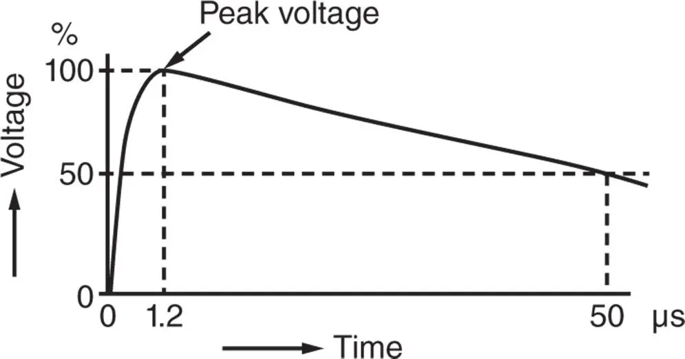
Figure 2.16 BIL impulse wave shape.
Table 2.4 System BILs.
| System (kV) | BIL (kVpeak) |
| 11 | 75 |
| 13.8 | 95/110 |
| 33 | 200 |
| 66 | 450 |
| 132 | 650/750 |
| 230 | 900/1050 |
2.11.1 Substation Shielding
The switchyard design for over voltage protection in addition to employing the protective equipment should also be shielded (protection coverage) to force the lightning strikes to hit the masts or shielding wires strung between the shielding masts, and not the operating equipment. Utilities typically have an area charted for flash density as Zones 1 and 2, which generally corresponds to the isokeraunic levels of the region and which can be applied on this project (see Chapter 10). Substations in Zone 2 area must be shielded with overhead shield wires or lightning masts.
Based on the criteria ( Chapter 10) and the method of grounding, the equipment shall be protected by the lightning arresters having the following ratings (see Table 2.5):
Table 2.5 System lightning arresters.
| Grid | 13 kV Transformer | O/H lines | 4.16 kV Switchgear | |
| Voltage (kV) | 230 | 13.8 | 13.8 | 4.16 |
| Highest voltage (kV) | 245 | 15 | 15 | 5 |
| Grounding | Solid | Resistance | Resistance | Resistance |
| BIL (kV) | 900 | 95 | 110 | 60 |
| MCOV a)(kV) | 150 | 15 | 15 | — |
| V r rating (kV) | 188 | 18 | 18 | — |
| Type (class) | Station | Line | Distr. | Not Req. b) |
| Discharge current (kA) | 10 | 5 | 5 | — |
a)It is the maximum continuous operating voltage r.m.s. (root mean square) voltage that can be continuously applied to the arrester terminals. The selection must consider the voltage regulation that may be applicable to the operating system.
Читать дальшеИнтервал:
Закладка:
Похожие книги на «Practical Power Plant Engineering»
Представляем Вашему вниманию похожие книги на «Practical Power Plant Engineering» списком для выбора. Мы отобрали схожую по названию и смыслу литературу в надежде предоставить читателям больше вариантов отыскать новые, интересные, ещё непрочитанные произведения.


Обсуждение, отзывы о книге «Practical Power Plant Engineering» и просто собственные мнения читателей. Оставьте ваши комментарии, напишите, что Вы думаете о произведении, его смысле или главных героях. Укажите что конкретно понравилось, а что нет, и почему Вы так считаете.