Zark Bedalov - Practical Power Plant Engineering
Здесь есть возможность читать онлайн «Zark Bedalov - Practical Power Plant Engineering» — ознакомительный отрывок электронной книги совершенно бесплатно, а после прочтения отрывка купить полную версию. В некоторых случаях можно слушать аудио, скачать через торрент в формате fb2 и присутствует краткое содержание. Жанр: unrecognised, на английском языке. Описание произведения, (предисловие) а так же отзывы посетителей доступны на портале библиотеки ЛибКат.

- Название:Practical Power Plant Engineering
- Автор:
- Жанр:
- Год:неизвестен
- ISBN:нет данных
- Рейтинг книги:5 / 5. Голосов: 1
-
Избранное:Добавить в избранное
- Отзывы:
-
Ваша оценка:
Practical Power Plant Engineering: краткое содержание, описание и аннотация
Предлагаем к чтению аннотацию, описание, краткое содержание или предисловие (зависит от того, что написал сам автор книги «Practical Power Plant Engineering»). Если вы не нашли необходимую информацию о книге — напишите в комментариях, мы постараемся отыскать её.
The book explores the most relevant topics and reviews the industry standards and established engineering practices. For example, the author leads the reader through the application of MV switchgear, MV controllers, MCCs and distribution lines in building plant power distribution systems, including calculations of interrupting duty for breakers and contactors. The text also contains useful information on the various types of concentrated and photovoltaic solar plants as well as wind farms with DFIG turbines. This important book:
• Explains why and how to select the proper ratings for electrical equipment for specific applications
• Includes information on the critical requirements for designing power systems to meet the performance requirements
• Presents tests of the electrical equipment that prove it is built to the required standards and will meet plant-specific operating requirements
Written for both professional engineers early in their career and experienced engineers,
is a must-have resource that offers the information needed to apply the concepts of power plant engineering in the real world.
Practical Power Plant Engineering — читать онлайн ознакомительный отрывок
Ниже представлен текст книги, разбитый по страницам. Система сохранения места последней прочитанной страницы, позволяет с удобством читать онлайн бесплатно книгу «Practical Power Plant Engineering», без необходимости каждый раз заново искать на чём Вы остановились. Поставьте закладку, и сможете в любой момент перейти на страницу, на которой закончили чтение.
Интервал:
Закладка:
Calculate voltage drop ratio corresponding to the motor/cable impedance ratio:
Therefore, the voltage % on motor terminals during the motor start is equals to 91.8% OK!For motor cable 100 m long: ΔV = 8.2% < 15% allowed.
This calculation assumed the 480 V bus is operating at 100% voltage at the time the motor is initiated to start.
2.7.12.3 Conclusion
This motor operating with the proposed cable 3c #1/0 AWG is acceptable for the actual cable length of 100 m. If the distance is doubled to 200 m, a new heavier cable would have to be selected as the Δ V = 16.4% > 15% is over the operating limit.
2.7.13 Overhead Distribution Lines
The major part of the power distribution between the main substation and the remote areas and the main process plant will be by overhead distribution lines. The lines will follow the most direct routes or along the roads to facilitate ease of construction and maintenance. The 13.8 kV feeders will be laid out either as radial feeders or ring main loop feeders to connect several unit substations and other major loads in a loop fed from two different sources.
The MV distribution lines will use wood poles and wood cross‐arms (see Figure 2.12). In tropics, use concrete poles and steel cross‐arms (see Chapter 9). The distribution lines will use Hawk ACSR 466 kcmil (660 A), or Partridge ACSR 266 kcmil bare conductor having more than 470 A capacity in free air and high pulling strength. High capacity conductors are used not only to maintain low voltage drops but also for their tensile strength for pulling and to be able to implement longer spans between poles.
The lines will be protected from lightning by an overhead shield wire on the top. The shield wire, popularly called overhead power ground wire (OPGW), will also contain fiber optic single mode, multicore cable inside it. All the metallic pole hardware will be grounded to a pole ground wire, which will then be led to the pole grounding rods. Depending on the soil conditions, the grounding rods will be installed at every pole in the dry areas and every several poles in the moist, low soil resistive areas.
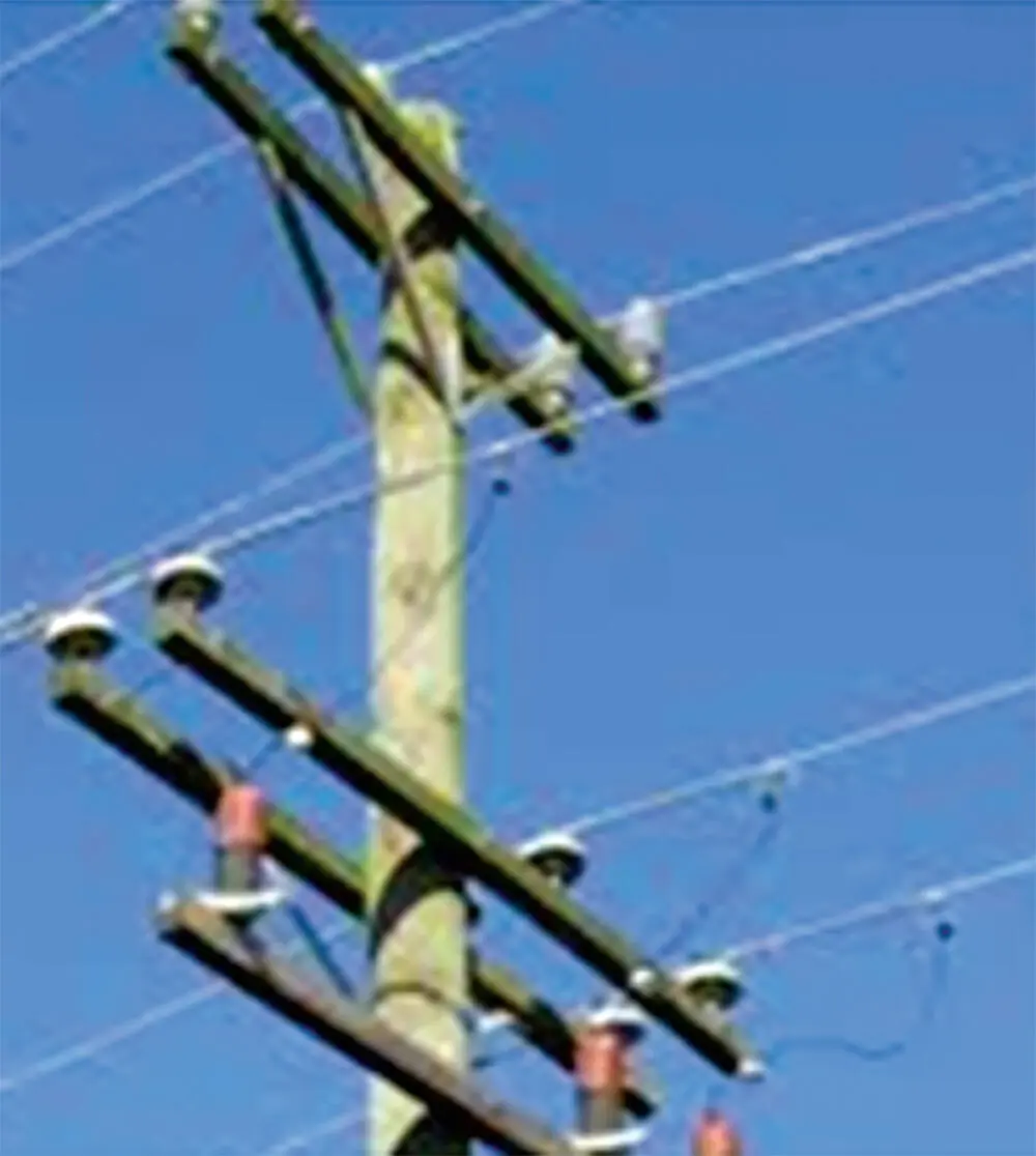
Figure 2.12 Distribution line.
2.8 Transformer System Grounding
Earlier in this section, we chose the main (grid) transformers to have YNd1 winding configurations. We did not explain the reasons for our specific choice. Let us clarify it. The method of system grounding is a critical issue of every electrical installation and it must be defined for each voltage level. The transformer winding configuration plays an essential role in this matter. The system grounding (equipment neutrals) has evolved over the years by using different methods of high resistance to no resistance grounding. In the last 20 years, the industry has basically standardized on the following methods:
| Transmission level, 69 kV and higher | Solid (zero resistance) → No fault limitation |
| MV 3.3–33 kV | Resistance → Limitation to 100 A |
| LV 400–600 V | Solid (zero resistance) → No Limitation |
| Generators, 5 kV and higher | High resistance → Limitation to 5–10 A |
The zero resistance (solid) grounding is now officially called “effective grounding.”
In some parts of the world, the LV systems for manufacturing plants are left ungrounded or resistance grounded to allow the plant operation to continue, but to clear the fault at some convenient time. A phase to phase fault occurs if the plant receives another fault on a different phase. In that case, the affected part of the plant is tripped.
Brief reasoning for the above methods of grounding and standardization are given below. For further discussion on the above standardization (see Chapter 5).
2.8.1 Transmission Level
The HV and EHV equipment at this voltage level is expensive. The transformer γ/Δ winding configuration with solid (effective) grounding with no resistance on the primary winding allows the manufacturers to apply lower BIL levels for the HV windings and to lower the cost of transformers and other equipment. The line tower footing ground resistance must also be kept low to reduce the BIL level of the line, thus cutting the cost of towers while offering the use of lower clearances and shorter insulator strings.
2.8.2 MV Systems
Having established the grid transformation to be γ/Δ for the primary distribution, the 13.8 kV delta system becomes ungrounded. A stable and detectable grounding system is required for this project, to insure the neutral point will not be floating in case of a ground fault. This can be accomplished by grounding/station service transformers. These will be 300 kVA, 13.8 kV to 480 V, Z g/γ with a 100 A grounding resistor on the primary. The secondary neutral is grounded directly to ground without a resistor to render a four‐wire system, suitable for the LV 277/480 V services.
The grounding/station service transformers are connected to the 13.8 kV buses with fused links.
The MV 13.8 to 4.16 kV transformers are Δ/γ. The LV neutral is resistance grounded to limit the fault current to about 100 A. The selected fault current is low enough to limit the damage caused by ground faults to the MV equipment and high enough to be used for selective relay protection and most importantly to limit the insulation overstressing due to spiking arcing ground faults caused by the system capacitances.
2.8.3 LV Systems
The LV systems will use 13.8 kV to 480 V, Δ/γ transformers. The LV (star) side will be solidly grounded with no intentional resistance. This will cause the ground fault currents to be as high as phase fault currents and can be operated by the phase current protection. In the mining industry, LV neutrals are resistance grounded as shown in Figure 2.10.
2.8.4 Generator Neutrals
This is addressed in more details in Chapter 5.
The standby DG may be grounded as the MV system to limit the fault current to 100 A.
2.9 Transformer Winding Configurations and Phasing
Based on the foregoing discussion, the plant distribution transformer selection will be as follows:
Grid transformers (2): 230 to 13.8 kV, YNd1, 30/40 MVA, ONAN/ONAF, oil Immersed, solidly grounded.
Process plant transformers (2): 13.2 to 4.16 kV, Dyn11, 12/15 MVA, ONAN/ONAF, oil immersed, 100 A grounding resistor. Figure 2.13 Plant phasing diagram.
Plant transformers (2): 4.16 kV to 480 V, Dyn11, 2/3 MVA, ONAN/ ONAF, dry type, solidly grounded.
Plant transformers (7): 13.2 kV to 480 V, Dyn11, 1/1.5 MVA,
ONAN/ONAF, dry type, solidly grounded.
Note Figure 2.13, we have selected lagging (−30°) winding configuration for the grid transformers and leading (30°) for the plant transformers. This will make the secondary voltage (4.16 kV) of the second‐level plant transformers in phase with the 230 kV grid voltage.
Furthermore, note that all the 480 V buses are not in phase. Those fed from the 13.8 kV buses are 30° apart from those fed from the 4.16 kV buses: for instance T41 and T31, respectively.
It is important to note that the 480 V buses from those transformers cannot be interconnected together. On our project in this book, this type of phasing may not be important, as the plant power distribution system is of radial nature without a need for synchronizing.
In other larger plants, where there is a requirement for synchronizing, it is essential to establish proper transformer winding configurations to suit. Engineers must learn how to assign correct transformer winding configuration and phasing orientation for the transformers on the electrical diagrams.
Читать дальшеИнтервал:
Закладка:
Похожие книги на «Practical Power Plant Engineering»
Представляем Вашему вниманию похожие книги на «Practical Power Plant Engineering» списком для выбора. Мы отобрали схожую по названию и смыслу литературу в надежде предоставить читателям больше вариантов отыскать новые, интересные, ещё непрочитанные произведения.


Обсуждение, отзывы о книге «Practical Power Plant Engineering» и просто собственные мнения читателей. Оставьте ваши комментарии, напишите, что Вы думаете о произведении, его смысле или главных героях. Укажите что конкретно понравилось, а что нет, и почему Вы так считаете.