Zark Bedalov - Practical Power Plant Engineering
Здесь есть возможность читать онлайн «Zark Bedalov - Practical Power Plant Engineering» — ознакомительный отрывок электронной книги совершенно бесплатно, а после прочтения отрывка купить полную версию. В некоторых случаях можно слушать аудио, скачать через торрент в формате fb2 и присутствует краткое содержание. Жанр: unrecognised, на английском языке. Описание произведения, (предисловие) а так же отзывы посетителей доступны на портале библиотеки ЛибКат.

- Название:Practical Power Plant Engineering
- Автор:
- Жанр:
- Год:неизвестен
- ISBN:нет данных
- Рейтинг книги:5 / 5. Голосов: 1
-
Избранное:Добавить в избранное
- Отзывы:
-
Ваша оценка:
Practical Power Plant Engineering: краткое содержание, описание и аннотация
Предлагаем к чтению аннотацию, описание, краткое содержание или предисловие (зависит от того, что написал сам автор книги «Practical Power Plant Engineering»). Если вы не нашли необходимую информацию о книге — напишите в комментариях, мы постараемся отыскать её.
The book explores the most relevant topics and reviews the industry standards and established engineering practices. For example, the author leads the reader through the application of MV switchgear, MV controllers, MCCs and distribution lines in building plant power distribution systems, including calculations of interrupting duty for breakers and contactors. The text also contains useful information on the various types of concentrated and photovoltaic solar plants as well as wind farms with DFIG turbines. This important book:
• Explains why and how to select the proper ratings for electrical equipment for specific applications
• Includes information on the critical requirements for designing power systems to meet the performance requirements
• Presents tests of the electrical equipment that prove it is built to the required standards and will meet plant-specific operating requirements
Written for both professional engineers early in their career and experienced engineers,
is a must-have resource that offers the information needed to apply the concepts of power plant engineering in the real world.
Practical Power Plant Engineering — читать онлайн ознакомительный отрывок
Ниже представлен текст книги, разбитый по страницам. Система сохранения места последней прочитанной страницы, позволяет с удобством читать онлайн бесплатно книгу «Practical Power Plant Engineering», без необходимости каждый раз заново искать на чём Вы остановились. Поставьте закладку, и сможете в любой момент перейти на страницу, на которой закончили чтение.
Интервал:
Закладка:
Transformer oil: Transformers oil is tested for its dielectric strength several days prior to energizing. New oil should have a strength of >65 kV/cm, while older oils must demonstrate the insulating strength of >60 kV/cm. If the strength is lower than those desired, the transformer oil must be purified by the heating and filtering equipment to exhaust the moisture before energizing. Oil samples will be taken from the transformer during installation a week before energizing.
Figure 1.6presents an actual handover chart of a power plant from construction, through precommissioning, commissioning, and reliability run (RR) to operation and ownership transfer.
The precommissioning checks on a larger piece of equipment, for instance, a large hydroelectric generator, is a relatively complex endeavor. A large number of interlocks must be simulated, much of them from the software. Some precommissioning can be done and must be done, such as unit trip logic and emergency stops and safety trips. In order to make the simulations more manageable, control functions are usually broken down into a number of sequential steps. These critical offline tests are performed before the online tests are attempted in order to minimize any unforeseen inadvertent operation. During this process, the unit is tested through a restricted logic to allow the checks on part of the logic and then proceed to the next ever larger step. The rest is left for commissioning. Since there are too many interlocks to be dealt with, there is also a fear that some of the simulation jumpers may be forgotten and left behind. Jumpered contacts left behind hide unreal bypassed conditions.
1.3.2 Commissioning
Commissioning is often called wet commissioning. It is an engineering activity that follows the precommissioning phase, often called dry commissioning. Commissioning is an engineering activity dedicated to testing the plant or part of the plant, in a fully energized state of applied electricity, pressure, heat, steam, and water with all the auxiliary systems in service.
During the days of relay logic and manual plant control, the commissioning was not that extensive. Nowadays, the plants have become fully automated and generally unmanned, having inputs from numerous field devices, start, stop, overload, ready, local/remote (Loc/Rem), breaker position, trip, analogs, etc. To diagnose the plant directly on the operator's screen rather than by pulling, simulating, and jumpering, the wires in the panels takes a lot of coordinated effort in many parts of the plant at the same time.
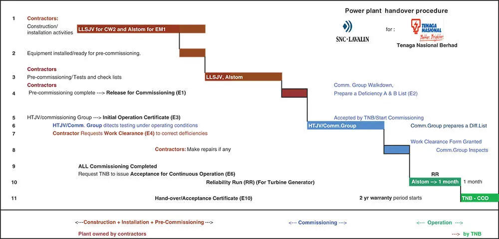
Figure 1.6 Plant handover procedure.
Source: Courtesy of SNC‐Lavalin.
Only a fully energized condition offers a controlled testing environment that allows all the logic elements to be properly commissioned and proven. This work in a noisy environment requires good communications between all the parties. Often, the cell phones do not work due to the noise interference. On the last project, the proper communication was only achieved after the house telephones operating on fiber optic cables were installed.
Primary injection: Commissioning of large power plants carries considerable risks and safety issues. This is because commissioning is mostly performed under the primary injection when the equipment is fully energized. The operating voltage is applied, and the currents are flowing through the cables and breakers. This flow can now be monitored on the real front panel instruments and/or relays. The flow of current (power) can be changed by loading the feeders and circuit breakers.
While most of the precommissioning and troubleshooting is performed from the schematic diagrams, just like always has been, the commissioning is performed based on the operational requirements. Commissioning as mentioned above is energizing and testing of the groups of equipment working together under active pressure of oil, water, steam, air, or electricity, with a minimum of simulation. This is the first time the equipment and the control system will face fuel, water, air, oil, and electricity. Believe me, this makes a lot of difference in the equipment behavior, particularly the instrumentation. The instrumentation finally gets to be checked for flow, speed, voltage, pressure, etc. Some of the instruments will now prove to be faulty, poorly calibrated, or incorrectly selected, or perhaps incorrectly wired or leaking.
The precommissioning of the power plant control system is mostly skipped in favor of the commissioning as mentioned earlier when the generator is energized in a controlled manner and tested.
Most of the wiring or control logic (95%) is expected to be correct, but a small part (5%) may be incorrect. The operator's screen may not indicate an error, but it will show what is not functioning or functioning incorrectly. It is not an easy task to comprehend as multiple malfunctions may be a result of a single wrong input. But which? Where to start? The logic interlock strings have to be investigated by observing the schematics, by removing the wired and software interlocks, one interlock at a time to zoom in on the possible targets or “usual suspects.”
What are the interlocks? These are the “permissives” that enable or disable another drive. This may be a case of set of pumps of which one only is allowed to run at any time. Safety Interlocks are hard wired into the electrical circuits as in Figure 1.7. Process interlocks are entered into software as shown on the right.
Sometimes, missing wiring must be added, wires reversed, corrected, removed, and jumpered to make it correct according to the schematics.
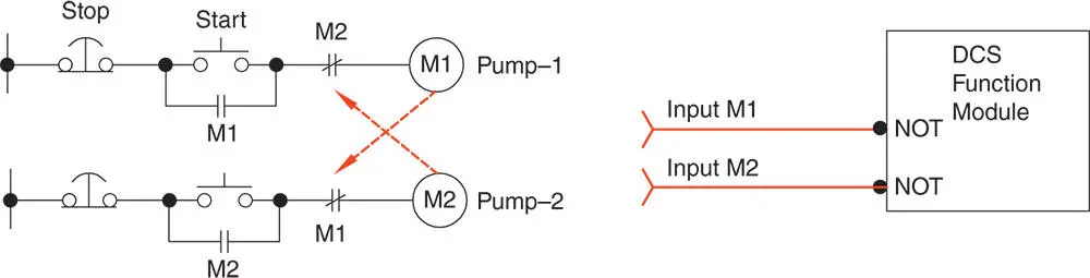
Figure 1.7 Plant interlocks, hard wired and software.
And if it still does not work, then the schematic must be corrected and the circuit rewired. Often, an interposing relay may not be seating properly. There are so many ways to fail?
The wiring tabulations, mentioned earlier, are generally not being updated. The schematics are updated in red and issued “As Built.” The commissioning approach, though relatively cumbersome, avoids all the simulations to be done and saves the time as the work is concentrated on fixing faulty wiring and wrong logic lines only, and not on all the wiring and all the logic. This approach may work providing the unit was being fully tested under all the operating conditions of loading, ramping, and stopping to expose the functioning of all the instrumentation, the transmitters, and indicating instruments. The transmitters may work correctly for certain loading and operating sequences, but rapid changes in the load may expose their weaknesses.
In my judgment, the following are typical commissioning problems:
1 Mechanical: Rare. They tend to be visible, but take longer (days) to fix and replace with spare parts if available.
2 Electrical wiring: Due to wrong wiring, wrong schematics, inappropriate contact seating. This is diagnosed by going over the schematics and fixed within hours.
3 Control logic software errors. This is diagnosed and modified within hours. Often, several attempts are tried.
4 Nonresponsive devices (level switches, analogs, pressure switches, transmitters, etc.). The devices may be faulty or inappropriate for the application. These problems are relatively common and difficult to deal with because of their unpredictable and intermittent behavior. These issues may take several days to be discovered, repaired, and the fix confirmed when repaired.
Читать дальшеИнтервал:
Закладка:
Похожие книги на «Practical Power Plant Engineering»
Представляем Вашему вниманию похожие книги на «Practical Power Plant Engineering» списком для выбора. Мы отобрали схожую по названию и смыслу литературу в надежде предоставить читателям больше вариантов отыскать новые, интересные, ещё непрочитанные произведения.


Обсуждение, отзывы о книге «Practical Power Plant Engineering» и просто собственные мнения читателей. Оставьте ваши комментарии, напишите, что Вы думаете о произведении, его смысле или главных героях. Укажите что конкретно понравилось, а что нет, и почему Вы так считаете.