Zark Bedalov - Practical Power Plant Engineering
Здесь есть возможность читать онлайн «Zark Bedalov - Practical Power Plant Engineering» — ознакомительный отрывок электронной книги совершенно бесплатно, а после прочтения отрывка купить полную версию. В некоторых случаях можно слушать аудио, скачать через торрент в формате fb2 и присутствует краткое содержание. Жанр: unrecognised, на английском языке. Описание произведения, (предисловие) а так же отзывы посетителей доступны на портале библиотеки ЛибКат.

- Название:Practical Power Plant Engineering
- Автор:
- Жанр:
- Год:неизвестен
- ISBN:нет данных
- Рейтинг книги:5 / 5. Голосов: 1
-
Избранное:Добавить в избранное
- Отзывы:
-
Ваша оценка:
Practical Power Plant Engineering: краткое содержание, описание и аннотация
Предлагаем к чтению аннотацию, описание, краткое содержание или предисловие (зависит от того, что написал сам автор книги «Practical Power Plant Engineering»). Если вы не нашли необходимую информацию о книге — напишите в комментариях, мы постараемся отыскать её.
The book explores the most relevant topics and reviews the industry standards and established engineering practices. For example, the author leads the reader through the application of MV switchgear, MV controllers, MCCs and distribution lines in building plant power distribution systems, including calculations of interrupting duty for breakers and contactors. The text also contains useful information on the various types of concentrated and photovoltaic solar plants as well as wind farms with DFIG turbines. This important book:
• Explains why and how to select the proper ratings for electrical equipment for specific applications
• Includes information on the critical requirements for designing power systems to meet the performance requirements
• Presents tests of the electrical equipment that prove it is built to the required standards and will meet plant-specific operating requirements
Written for both professional engineers early in their career and experienced engineers,
is a must-have resource that offers the information needed to apply the concepts of power plant engineering in the real world.
Practical Power Plant Engineering — читать онлайн ознакомительный отрывок
Ниже представлен текст книги, разбитый по страницам. Система сохранения места последней прочитанной страницы, позволяет с удобством читать онлайн бесплатно книгу «Practical Power Plant Engineering», без необходимости каждый раз заново искать на чём Вы остановились. Поставьте закладку, и сможете в любой момент перейти на страницу, на которой закончили чтение.
Интервал:
Закладка:
There are a number of methods on how to number the equipment. Some clients may have their own numbering system for all of their projects. The numbering is generally done by the mechanical department, except for the purely electrical equipment, which is numbered by the electrical group. The most popular numbering systems are the intuitive systems, as follows:
Example: 20 PU 007; Area 20; PUmp sequence number: 007. The pump number is also given to the associated motor.
The plant process areas may be given the specific area designations:
00: For a general site, including the main substation
10: Crushing
20: Conveying
30: Milling
40: Flotation, etc.
For the equipment, assign intuitive designations as follows:
PU, pump; SP, sump pump; TK, tank; CR, crane; AG, agitator; VF, vent fan; RF, roof fan; LP, lighting panel; HR, heater; CV, conveyor; TR, transformer; CY, cyclone; etc.
The sequence is from 001 to 999. The sequence numbering may restart from 001 for each area.
The numbers do not have to be consecutive. The sequence number 001 may start from the basement, 101 on the first level, etc., to better describe the equipment location.
Be consistent and make sure the pumps are sequenced in pairs: 001/002, 103/104, the odd number is, for instance, on the left side approaching the motors.
Cables are generally numbered and defined by the loads and not the MCC sources. Some companies insist that cable numbers include indications of the source (the MCC bucket) and the destination (load). Standardize control cables for the common hardware such as pushbuttons by using consistent cable C suffixes, programmable logic controller (PLC) connections. For instance, the cables for the pump 40 PU 003 are labeled:
40 PU 003 P: For the motor power cable.
40 PU 003 C1: For the control cable to PLC equipment.
40 PU 003 C2: For the control cable to the Push Button station.
40 PU 003 C3: For the control cable to the field level switch or other sensor.
Make sure the numbering is consistent for all plant motors. This will allow for easier understanding of the plant cabling and purposes. For instance, establish that cable C1 for all the plant motors is always the cable from the motor starter going to PLC. If that cable is not used, that number is skipped for that particular drive. Push button station always occupies cable C2, etc. This consistent method of numbering will help you computerize the cable lists and to sort the lists to specific equipment.
The equipment numbers are needed to create load lists, which will later be expanded to create the list of schematics and cable lists. For instance by adding to the list of loads: the load names, voltage, kW rating, MCC, and bucket, a computer program can create a list of cables, select the cable sizes, and assign “From – To” destinations without any manual input.
If you add a typical schematic diagram type for each drive or feeder to the load list, the computer program will assign and fill in the cables and cable details on the drawings for each particular drive/feeder without any human input.
1.2.7 Load List
Based on the data given in the load list ( Table 1.1), the computer calculates the cable size, type, length, and routing (see Table 1.2).
Adopt minimum cable sizes: #12 American wire gauge (AWG) for power and #16 AWG for controls.
Should the kW rating change and a new kW rating be entered into the list, the cable size will be computer‐updated automatically when the cable list is regenerated.
The same computer program generates and prints the schematic and wiring diagrams automatically adding to the drawing of all the specific data including the cable data, input/output (I/O) data, and wiring terminations.
1.2.8 Generated Cable List
Table 1.1 Load list (simplified).
| ID | Name | Volt | kW | MCC | In service | Type |
| 40 PU 003 | Feed Pump, Water Tank 1 | 460 | 15 | MCC11 | 1 | T1 |
| 40 PU 004 | Feed Pump, Water Tank 1 | 460 | 15 | MCC11 | SB | T1 |
| 30 AG 006 | Agitator, Tank 6 | 460 | 10 | MCC03 | 1 | T1 |
| 30 CR 001 | Crane, 60 Tone, Main Hall | 460 | 100 | MCC03 | 1 | F1 |
| 10 RF 003 | Crusher Roof Fan | 460 | 1 | MCC 01 | 1 | T3 |
In service: 1 = operating, SB = on standby.
Type: this is the designation of the type of operating circuit to be implemented.
Table 1.2 Cable list (simplified).
| Cable ID | Cable size | kW | Type/class | From | To | Length |
| 40 PU 003 P | 1‐3/c #10 AWG, | 20 | Teck 600V | MCC11 | PU Motor | 120 |
| 40 PU 003 C1 | 1‐5/c #16 AWG, | Teck 300V | MCC11 | PLC 2 | 15 | |
| 40 PU 003 C2 | 1‐3/c #14 AWG, | Teck 300V | MCC11 | PB Stn | 120 | |
| 40 PU 004 P | 1‐3/c #10AWG, | 20 | Teck 600V | MCC11 | PU Motor | 120 |
| 40 PU 004 C1 | 1‐5/c #16 AWG, | Teck 300V | MCC11 | PLC 2 | 15 | |
| 40 PU 004 C2 | 1‐3/c #14 AWG, | Teck 300V | MCC11 | PBStn | 120 | |
| 40 PU 004 C3 | 1‐2/c #14 AWG, | Teck 300V | MCC11 | TH1 | 130 | |
| 30 AG 005 P | 1‐3/c #12AWG, | 15 | Teck 600V | MCC05 | PU Motor | 85 |
| 30 AG 005 C1 | 1‐5/c #16 AWG, | Teck 300V | MCC05 | PLC 3 | 20 | |
| 30 AG 005 C2 | 1‐3/c #14 AWG, | Teck 300V | MCC05 | PB Stn | 85 | |
| 10 SP 003 P | 1‐3/c # 12 AWG, | 5 | Teck 600V | MCC01 | PU Motor | 60 |
| 10 SP 003 C2 | 1‐3/c #14 AWG, | Teck 300V | MCC01 | PB Stn | 60 |
1.2.9 Schematic/Wiring Diagrams
In the last 20 years, the schematic and wiring diagrams have changed in the following ways. This author has participated on all three of them:
1 Relay logic diagram. That is past. We will not dwell on this wiring approach any more.
2 Connection to PLC I/O (see Figure 1.3)
3 Connection to distributed control system (DCS) communication modules (see Figure 1.4).
It is not known whether there is a forth step around the corner, but it could be said that each advance has brought us considerable progress and simplification to the design of the schematic/wiring diagrams.
Specific operating logic for each motor and valve is no longer needed to be shown in the diagrams as it used to be with the relay logic diagrams. The circuits ( Figure 1.3) were drawn and wired uniformly into DCS or PLC I/O cards, while the specific logic to each drive is developed as software. Though this method needs less wiring and it is made to be uniform, there is still plenty of wiring to be done.
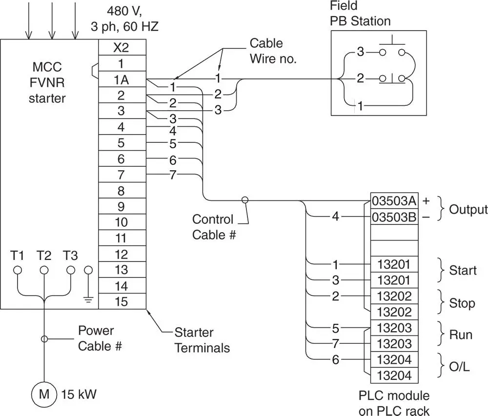
Figure 1.3 Motor wiring diagram with PLC module.
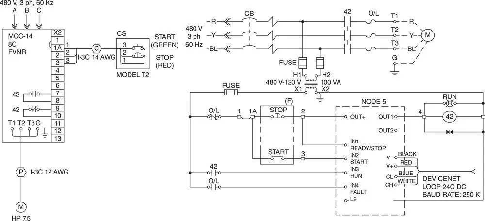
Figure 1.4 Motor wiring diagram to DeviceNet communication module.
Читать дальшеИнтервал:
Закладка:
Похожие книги на «Practical Power Plant Engineering»
Представляем Вашему вниманию похожие книги на «Practical Power Plant Engineering» списком для выбора. Мы отобрали схожую по названию и смыслу литературу в надежде предоставить читателям больше вариантов отыскать новые, интересные, ещё непрочитанные произведения.


Обсуждение, отзывы о книге «Practical Power Plant Engineering» и просто собственные мнения читателей. Оставьте ваши комментарии, напишите, что Вы думаете о произведении, его смысле или главных героях. Укажите что конкретно понравилось, а что нет, и почему Вы так считаете.