Zark Bedalov - Practical Power Plant Engineering
Здесь есть возможность читать онлайн «Zark Bedalov - Practical Power Plant Engineering» — ознакомительный отрывок электронной книги совершенно бесплатно, а после прочтения отрывка купить полную версию. В некоторых случаях можно слушать аудио, скачать через торрент в формате fb2 и присутствует краткое содержание. Жанр: unrecognised, на английском языке. Описание произведения, (предисловие) а так же отзывы посетителей доступны на портале библиотеки ЛибКат.

- Название:Practical Power Plant Engineering
- Автор:
- Жанр:
- Год:неизвестен
- ISBN:нет данных
- Рейтинг книги:5 / 5. Голосов: 1
-
Избранное:Добавить в избранное
- Отзывы:
-
Ваша оценка:
Practical Power Plant Engineering: краткое содержание, описание и аннотация
Предлагаем к чтению аннотацию, описание, краткое содержание или предисловие (зависит от того, что написал сам автор книги «Practical Power Plant Engineering»). Если вы не нашли необходимую информацию о книге — напишите в комментариях, мы постараемся отыскать её.
The book explores the most relevant topics and reviews the industry standards and established engineering practices. For example, the author leads the reader through the application of MV switchgear, MV controllers, MCCs and distribution lines in building plant power distribution systems, including calculations of interrupting duty for breakers and contactors. The text also contains useful information on the various types of concentrated and photovoltaic solar plants as well as wind farms with DFIG turbines. This important book:
• Explains why and how to select the proper ratings for electrical equipment for specific applications
• Includes information on the critical requirements for designing power systems to meet the performance requirements
• Presents tests of the electrical equipment that prove it is built to the required standards and will meet plant-specific operating requirements
Written for both professional engineers early in their career and experienced engineers,
is a must-have resource that offers the information needed to apply the concepts of power plant engineering in the real world.
Practical Power Plant Engineering — читать онлайн ознакомительный отрывок
Ниже представлен текст книги, разбитый по страницам. Система сохранения места последней прочитанной страницы, позволяет с удобством читать онлайн бесплатно книгу «Practical Power Plant Engineering», без необходимости каждый раз заново искать на чём Вы остановились. Поставьте закладку, и сможете в любой момент перейти на страницу, на которой закончили чтение.
Интервал:
Закладка:
From thereon, Zark was in his domain and in demand. Early on, he changed companies every three to four years to learn more. He worked for almost 50 years on large projects, power plants, and heavy industries, all around the world, employed by major international engineering companies, such as Bechtel, Fluor, Atomic Energy of Canada, SNC Lavalin, and often independent, teaching along the way and enjoying the work and life. Now retired, he writes on electricity and teaches young engineers on how the electricity makes the factories and power plants function.
1 Plant from Design to Commissioning
CHAPTER MENU
1.1 Planning 1.1.1 Plant Design Procedure 1.1.2 Codes and Standards
1.2 Project Development1.2.1 Type of Project 1.2.2 Conceptual Design for Feasibility Study 1.2.3 Detailed Design 1.2.4 Engineering Documents 1.2.5 Equipment Specifications and Data Sheets 1.2.6 Equipment Numbering 1.2.7 Load List 1.2.8 Generated Cable List 1.2.9 Schematic/Wiring Diagrams
1.3 Precommissioning and Commissioning 1.3.1 Precommissioning 1.3.2 Commissioning 1.3.3 Reliability Run 1.3.4 Power Plant Grid Tests 1.3.5 Commissioning Reports
1.4 Project Economics1.4.1 Budget Estimate 1.4.2 Levelized Cost of Energy (LCOE) 1.4.3 Marginal Cost of Energy 1.4.4 Profitability of an Industrial Plant
Reference
1.1 Planning
The electrical power distribution systems have to be designed to fit the plant electrical requirements. The power systems must be well planned, considering the technological process, cost, reliability, maintenance, control, operating flexibility, and future growth. Furthermore, the undertaking must take into account the safety of people and equipment, continuity of power supply, installation, and operating costs.
Electrical engineers' responsibility is to prepare design criteria and single‐line diagrams, power system studies, calculate fault currents, locate load centers within the plant, estimate load diversity, select the grounding system, define the routes of overhead lines, prepare plant layouts, and develop the electrical protection system, all of it to suit the plant location and the prevailing standards. Furthermore, he/she must procure the equipment and participate in the plant construction and commissioning.
The basic concept for a single‐line diagram representing the power plant power distribution is generally established by the utilities. The main engineering effort is on implementing the power system around the generating units. Depending on the generator unit MW size, a decision will be made on having generator breakers next to the generators or employing high voltage (HV) breakers instead, in the switchyard to serve as the unit breakers for the generator/transformer groups. That is one of the most significant factors that define the overall concept of the diagram. The power plant station service generally uses less than 5% of power of the generator MW rating, thus, the one‐line diagram for a power plant is relatively simple in comparison to the industrial plants (see Chapter 18for more details).
One‐line diagrams for industrial plants vary significantly from industry to industry. The load is fully distributed around the various operating activities, such as crushing, grinding, mixing, drying, pumping, batching, each of which requires a considerable engineering effort and decision making process to arrive at an optimal economic diagram that can be scaled and readily expanded in the future.
This book is written in 26 chapters to cover all the technical aspects of electrical engineering and to transfer practical experience onto young electrical engineers. In order to present it in a meaningful way, the book explains the technical details around a fictitious, though realistic power plant and industrial projects. An industrial project offers a greater variety of requirements and lends itself better for practical analysis.
This analysis can be applied to other plants that use similar electrical equipment, such as transformers, motors, generators, variable frequency drives (VFDs), cables, switchgear, overhead lines, fire protection, control systems, grounding, lighting, etc.
The project is commenced by an investor (company) who have decided to build a power or an industrial plant (cement factory, steel manufacturing, oil refinery, wood mill, plastic cups, fruit canning, etc.) on a particular location for a particular operating capacity (produced MW, tons of cement, tons of steel, tons of paper, tons fruit, etc.).
The investor company had already prepared a rough estimate proposal for a project with a simple budget estimate of ±40% accuracy and had received positive indications of financing from a bank to develop a feasibility study and a more detailed cost estimate. Figure 1.1shows the steps of the project development.
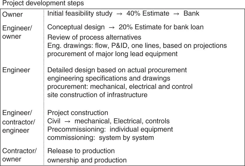
Figure 1.1 Project development.
From the electrical power system perspective, the first step is to review the project flow diagrams produced by mechanical engineers and on that basis prepare electrical design criteria and develop a key one‐line diagram(see Chapter 2). The key one‐line diagram will envelop all the process facilities within the plant starting from the power source down to the individual equipment users and services. This is followed by preparing a (±20%) budget cost estimate as part of the conceptual design inclusive of the cost for engineering and construction and then present it to the bank to secure a loan.
1.1.1 Plant Design Procedure
Plant design is a joint effort by multiple engineering disciplines: process, mechanical, civil, electrical, architectural, structural, estimating, scheduling, procurement, document controls, and project management. Every department is doing its work in strict coordination with others to insure everyone is “on the same page” and that nothing falls “between the cracks.” Lead engineers of all the disciplines are on the email circulation of everything that is happening on the project to insure all the design decisions and project changes are being communicated and implemented, both “vertically and horizontally” through the project organization chart. Regular meetings are held on a weekly basis to assess the progress, critical path schedule, any design changes, manpower shortfalls, and any delays in design, procurement, fabrication, and installation and their impact on the project schedule. Design options and temporary measures are being reviewed to overcome the delays in the equipment deliveries and/or equipment failures.
1.1.2 Codes and Standards
The publications listed below form a part of this book. Each publication shall be the latest revision and addendum in effect at the time of issue of contract and design specifications, unless noted otherwise.
| ANSI | American National Standards Institute |
| CSA | Canadian Standards Association |
| IEEE | Institute of Electrical and Electronic Engineers |
| IEC | International Electro‐technical Commission |
| ISA | Instrument Society of USA |
| ISO | International Standards Organization |
| NACE | The Worldwide Corrosion Authority |
| NEMA | National Electrical Manufacturer's Association |
| NEC | National Electrical Code |
| NFPA | National Fire Protection Association |
| UL | Underwriters Laboratories of USA |
Standards, codes, and guidelines listed above and referenced in every chapter of this book are widely used by the engineers in the industry, both as directives and guides. When working in another country, the local standards must also be applicable. This book refers to and often presents data courtesy of these engineering standards, which are considered one of the major sources of guidelines and good engineering practices for engineers.
Читать дальшеИнтервал:
Закладка:
Похожие книги на «Practical Power Plant Engineering»
Представляем Вашему вниманию похожие книги на «Practical Power Plant Engineering» списком для выбора. Мы отобрали схожую по названию и смыслу литературу в надежде предоставить читателям больше вариантов отыскать новые, интересные, ещё непрочитанные произведения.


Обсуждение, отзывы о книге «Practical Power Plant Engineering» и просто собственные мнения читателей. Оставьте ваши комментарии, напишите, что Вы думаете о произведении, его смысле или главных героях. Укажите что конкретно понравилось, а что нет, и почему Вы так считаете.