Anil K. Chopra - Earthquake Engineering for Concrete Dams
Здесь есть возможность читать онлайн «Anil K. Chopra - Earthquake Engineering for Concrete Dams» — ознакомительный отрывок электронной книги совершенно бесплатно, а после прочтения отрывка купить полную версию. В некоторых случаях можно слушать аудио, скачать через торрент в формате fb2 и присутствует краткое содержание. Жанр: unrecognised, на английском языке. Описание произведения, (предисловие) а так же отзывы посетителей доступны на портале библиотеки ЛибКат.
- Название:Earthquake Engineering for Concrete Dams
- Автор:
- Жанр:
- Год:неизвестен
- ISBN:нет данных
- Рейтинг книги:4 / 5. Голосов: 1
-
Избранное:Добавить в избранное
- Отзывы:
-
Ваша оценка:
Earthquake Engineering for Concrete Dams: краткое содержание, описание и аннотация
Предлагаем к чтению аннотацию, описание, краткое содержание или предисловие (зависит от того, что написал сам автор книги «Earthquake Engineering for Concrete Dams»). Если вы не нашли необходимую информацию о книге — напишите в комментариях, мы постараемся отыскать её.
offers a comprehensive, integrated view of this progress over the last fifty years. The book offers an understanding of the limitations of the various methods of dynamic analysis used in practice and develops modern methods that overcome these limitations.
This important book:
Develops procedures for dynamic analysis of two-dimensional and three-dimensional models of concrete dams Identifies system parameters that influence their response Demonstrates the effects of dam–water–foundation interaction on earthquake response Identifies factors that must be included in earthquake analysis of concrete dams Examines design earthquakes as defined by various regulatory bodies and organizations Presents modern methods for establishing design spectra and selecting ground motions Illustrates application of dynamic analysis procedures to the design of new dams and safety evaluation of existing dams. Written for graduate students, researchers, and professional engineers,
offers a comprehensive view of the current procedures and methods for seismic analysis, design, and safety evaluation of concrete dams.
Earthquake Engineering for Concrete Dams — читать онлайн ознакомительный отрывок
Ниже представлен текст книги, разбитый по страницам. Система сохранения места последней прочитанной страницы, позволяет с удобством читать онлайн бесплатно книгу «Earthquake Engineering for Concrete Dams», без необходимости каждый раз заново искать на чём Вы остановились. Поставьте закладку, и сможете в любой момент перейти на страницу, на которой закончили чтение.
Интервал:
Закладка:
Presented in Chapter 11, the direct FEM has the great advantage over the substructure method in that is it applicable to nonlinear systems, thus permitting modeling of concrete cracking, as well as sliding and separation at contraction joints, lift joints, dam–foundation interface, and fissures in rock; however, it has the disadvantage in that it requires truncation of fluid and foundation domains, thus requiring absorbing boundaries to simulate their semi‐unbounded size. This method has been developed in a form that can be implemented in any commercial finite‐element code; thus, it is applicable to 3D models of all types of concrete dams: gravity, arch, and buttress. Validation of the Direct FEM applied to linear systems against the substructure method is also included in Chapter 11.
1.8 SCOPE AND ORGANIZATION
The primary goals of the book are: (i) develop dynamic analysis procedures to determine the response of concrete dams to ground shaking; (ii) identify factors that must be included in the response analyses; (iii) describe procedures for selecting ground motions for dynamic analyses; and (iv) illustrate application of these procedures to the seismic design of new dams and safety evaluation of existing dams. Ground shaking is the only earthquake hazard that is considered; excluded are hazards such as fault rupture under the dam or its abutments, and landslides around the reservoir that may cause overtopping of the dam.
The book is organized into three parts: I. Gravity Dams: Chapters 2– 7; II. Arch Dams: Chapters 8– 11; and III. Design and Safety Evaluation: Chapters 12– 14. Part Iand Part IIare developed to address the first two of the above‐stated goals for gravity dams and arch dams, respectively. The various topics covered in Chapters 2– 11were mentioned in the preceding sections.
Part IIIincludes three chapters. In Chapter 12, two levels of design earthquakes are defined and the performance requirements for the dam during each earthquake stated, among other topics. Chapter 13is concerned with construction of the target design spectrum as well as selection of an ensemble of three‐components of ground motions consistent with this spectrum. The book closes with Chapter 14where application of modern dynamic analysis procedures to four projects are summarized.
NOTES
1 †The first part of this section is adapted from a National Research Council report (1990).
2 ‡The word “foundation” denotes the rock that supports the dam.
3 †“Reservoir” is the place of storage, not the fluid itself.
Part I GRAVITY DAMS
2 Fundamental Mode Response of Dams Including Dam–Water Interaction
PREVIEW
The motions of a dam during an earthquake cause dynamic pressures in the impounded water that act on the upstream face of the dam to modify the dam motions, which in turn influence the hydrodynamic pressures. It is this interaction between the dam and water that is the subject of this chapter. Considering only the fundamental mode of vibration of the dam, we first develop a procedure for analysis of dam response including dam–water interaction. Thereafter, results for dam response are presented for a wide range of parameters that characterize the dam–water system. These results provide a basis to identify the effects of dam–water interaction and their influence on the vibration properties – natural vibration period and damping ratio – and on the response of concrete gravity dams to earthquake ground motion. Also investigated are the implications of neglecting compressibility of water, an approximation that enables representation of hydrodynamic effects by inertia forces associated with an added mass of water moving with the dam. Finally, we develop an equivalent single‐degree‐of‐freedom (SDF) system to model the response of dams including dam–water interaction that enables estimation of peak response directly from the earthquake response (or design) spectrum. Such an analysis is intended for preliminary design and safety evaluation of dams.
2.1 SYSTEM AND GROUND MOTION
The system considered consists of a monolith of a concrete gravity dam fixed (or clamped) to the horizontal surface of underlying rock, assumed to be rigid, and impounding a reservoir † of water with wave‐absorptive reservoir bottom ( Figure 2.1.1). We will initially study the planar vibrations of an individual monolith due to earthquake excitation, a simplification that is supported by observations of monoliths vibrating somewhat independently during the earthquake response of Koyna Dam (Chopra and Chakrabarti 1972) and forced vibration tests of Pine Flat Dam (Rea et al. 1975); this simplification is discussed further in Section 5.1. The system is analyzed under the assumption of linear behavior.
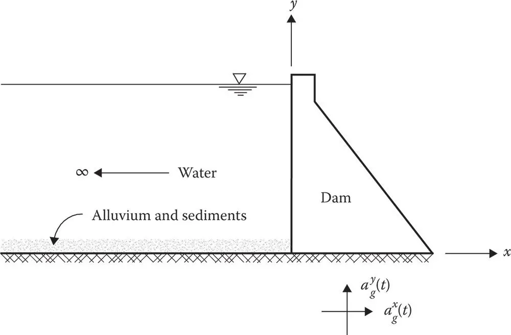
Figure 2.1.1Dam–water system.
The dam is idealized as a two‐dimensional finite element system, thus making it possible to consider arbitrary geometry and variation of material properties. However, certain restrictions on the geometry are imposed to permit a continuum solution of the hydrodynamic wave equation in the fluid domain. For the purpose of determining hydrodynamic effects, and only for this purpose, the upstream face of the dam is assumed to be vertical. This assumption is reasonable for most concrete gravity dams, because typically the upstream face is vertical or almost vertical for most of its height, and the hydrodynamic pressure on the dam face is insensitive to small departures of the face slope from being vertical, especially if these departures are in the lower part of the dam, which is usually the case. The impounded water in the reservoir is idealized by a fluid region of constant depth and infinite length in the upstream direction.
The bottom of a reservoir upstream from a dam is generally not rigid; its flexibility could arise from flexibility of the underlying foundation † or deposited sediments ( Figure 2.1.1). The reservoir bottom is approximately modeled by a boundary that partially absorbs incident hydrodynamic pressure waves; see Appendix 2.A for a description of this model.
The excitation for the two‐dimensional dam–water system is defined by the two components of free‐field ground acceleration in the plane of the monolith (or cross section) of the dam: the horizontal component  transverse to the longitudinal axis of the dam (i.e. in the stream direction) and the vertical component
  .
.
2.2 DAM RESPONSE ANALYSIS
2.2.1 Frequency Response Function
The displacements of the dam – relative to its base – vibrating in its fundamental vibration mode due to the l ‐component of ground motion ( l = x and y represents horizontal and vertical components, respectively) can be expressed as
(2.2.1) 
in which r x( x , y , t ) and r y( x , y , t ) are the horizontal and vertical components of displacement, respectively;  and
and  are the horizontal and vertical components, respectively, of the shape of the fundamental (or first) natural vibration mode of the dam fixed (or clamped) at its base to a rigid foundation with an empty reservoir; and
  is the modal coordinate associated with this vibration mode.
Интервал:
Закладка:
Похожие книги на «Earthquake Engineering for Concrete Dams»
Представляем Вашему вниманию похожие книги на «Earthquake Engineering for Concrete Dams» списком для выбора. Мы отобрали схожую по названию и смыслу литературу в надежде предоставить читателям больше вариантов отыскать новые, интересные, ещё непрочитанные произведения.


Обсуждение, отзывы о книге «Earthquake Engineering for Concrete Dams» и просто собственные мнения читателей. Оставьте ваши комментарии, напишите, что Вы думаете о произведении, его смысле или главных героях. Укажите что конкретно понравилось, а что нет, и почему Вы так считаете.