Anthony Kelly - Crystallography and Crystal Defects
Здесь есть возможность читать онлайн «Anthony Kelly - Crystallography and Crystal Defects» — ознакомительный отрывок электронной книги совершенно бесплатно, а после прочтения отрывка купить полную версию. В некоторых случаях можно слушать аудио, скачать через торрент в формате fb2 и присутствует краткое содержание. Жанр: unrecognised, на английском языке. Описание произведения, (предисловие) а так же отзывы посетителей доступны на портале библиотеки ЛибКат.
- Название:Crystallography and Crystal Defects
- Автор:
- Жанр:
- Год:неизвестен
- ISBN:нет данных
- Рейтинг книги:3 / 5. Голосов: 1
-
Избранное:Добавить в избранное
- Отзывы:
-
Ваша оценка:
Crystallography and Crystal Defects: краткое содержание, описание и аннотация
Предлагаем к чтению аннотацию, описание, краткое содержание или предисловие (зависит от того, что написал сам автор книги «Crystallography and Crystal Defects»). Если вы не нашли необходимую информацию о книге — напишите в комментариях, мы постараемся отыскать её.
explains the modern concepts of crystallography in a clear, succinct manner and shows how to apply these concepts in the analyses of point, line and planar defects in crystalline materials.
Fully revised and updated, this book now includes:
Original source references to key crystallographic terms familiar to materials scientists Expanded discussion on the elasticity of cubic materials New content on texture that contains more detail on Euler angles, orientation distribution functions and an expanded discussion on examples of textures in engineering materials Additional content on dislocations in materials of symmetry lower than cubic An expanded discussion of twinning which includes the description and classification of growth twins The inclusion and explanation of results from atomistic modelling of twin boundaries Problem sets with new questions, detailed worked solutions, supplementary lecture material and online computer programs for crystallographic calculations. Written by authors with extensive lecturing experience at undergraduate level,
continues to take its place as the core text on the topic and provides the essential resource for students and researchers in metallurgy, materials science, physics, chemistry, electrical, civil and mechanical engineering.
Crystallography and Crystal Defects — читать онлайн ознакомительный отрывок
Ниже представлен текст книги, разбитый по страницам. Система сохранения места последней прочитанной страницы, позволяет с удобством читать онлайн бесплатно книгу «Crystallography and Crystal Defects», без необходимости каждый раз заново искать на чём Вы остановились. Поставьте закладку, и сможете в любой момент перейти на страницу, на которой закончили чтение.
Интервал:
Закладка:
The two tetragonal lattices can be rapidly developed. The square net in Figure 1.14b has fourfold symmetry axes arranged at the corners of the squares and also at the centres. This fourfold symmetry may be preserved by placing the second net with a corner of the square at 00 z with respect to the first ( t 3normal to t 1and t 2) or with a corner of the square at  with respect to the first. The unit cells of the lattices produced by these two different arrangements are shown in Figures 1.19h and 1.19i, respectively. They can be designated P and I . The symbol I indicates a lattice with an additional lattice point at the centre of the unit cell (German: innenzentrierte ). In the tetragonal system the tetrad axis is usually taken parallel to c , so a and b are necessarily equal and all of the axial angles are 90°.
The nets shown in Figures 1.14d and 1.14e are each consistent with the symmetry of a diad axis lying at the intersection of two perpendicular mirror planes. It is shown in Section 2.1that a mirror plane is completely equivalent to what is called an inverse diad axis: a diad axis involving the operation of rotation plus inversion. This inverse diad axis, given the symbol  , lies normal to the mirror plane. The symmetry of a diad axis at the intersection of two perpendicular mirror planes could therefore be described as 2
  , indicating the existence of three orthogonal axes: one diad and two inverse diads. The lattice consistent with this set of symmetry operations will also be consistent with the arrangement 222 in the orthorhombic crystal system ( Table 1.3). 13To develop the lattices consistent with orthorhombic symmetry, therefore, the two relevant nets are the rectangular net ( Figure 1.14d) and the rhombus net ( Figure 1.14e). The positions of diad axes are shown on the right‐hand sides of Figures 1.14d and 1.14e. The rhombus net can also be described as the centred rectangular net.
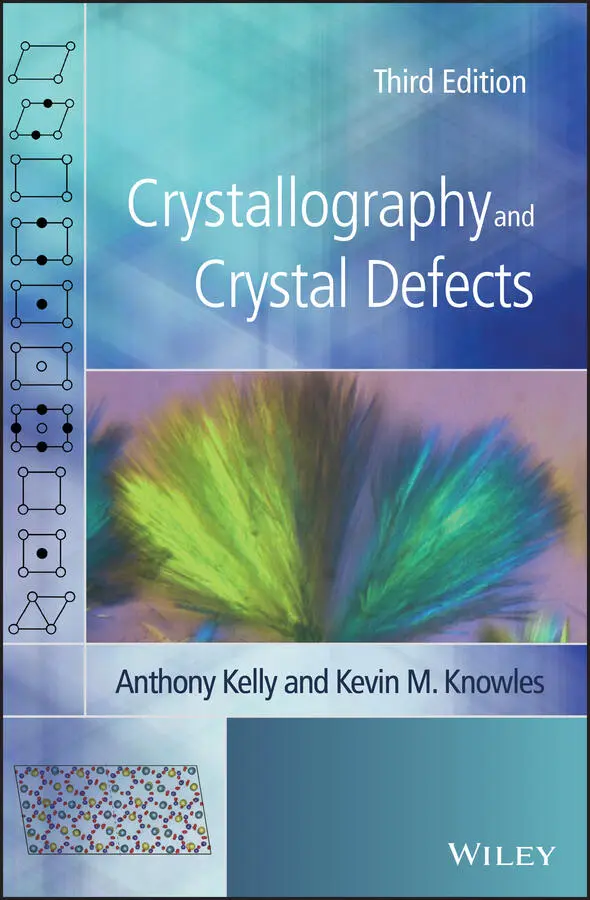
If we stack rectangular nets vertically above one another so that a corner lattice point of the second net lies vertically above a similar lattice point in the net at zero level ( t 3normal to t 1and t 2) then we produce the primitive lattice P . The unit cell is shown in Figure 1.19d. It is a rectangular parallelepiped.
If we stack rhombus nets (centred rectangles) vertically above one another, we obtain the lattice shown in Figure 1.23. This is the orthorhombic lattice with centring on one pair of faces.
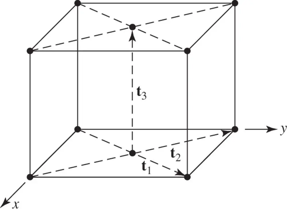
Figure 1.23The stacking of rhombus nets vertically above one another to form an orthorhombic lattice with centring on one pair of faces
We can also preserve the symmetry of a diad axis at the intersection of two mirror planes by stacking the rectangular nets in three staggered sequences. These are shown in Figures 1.24a, b and c. The lattices designated A ‐centred and B ‐centred are not essentially different since they can be transformed into one another by appropriate relabelling of the axes. 14The staggered sequence shown in Figure 1.24c is described by the unit cell shown in Figure 1.19f. It is the orthorhombic body‐centred lattice, symbol I . There is only one possibility for the staggered stacking of rhombus nets. Careful inspection of the right‐hand side of Figure 1.14e shows that the only places in the net where a diad axis lies at the intersection of two perpendicular mirror planes is at points with coordinates (0, 0) and  ,
,  of the rhombus primitive cell . We have already dealt with the vertical stacking of the rhombus nets. If we take the only staggered sequence possible, where the second net lies with a lattice point of the rhombus net vertically above the centre of the rhombus in the zero‐level net (so that the end of t 3has coordinates
  ,
,  , z in the rhombus net) then we produce the arrangement shown in Figure 1.25. This is most conveniently described in terms of a unit cell shown in Figure 1.19g, which is a rectangular parallelepiped with lattice points at the corners and also in the centres of all faces of the parallelepiped. This is the orthorhombic F cell. The symbol F stands for face‐centred, indicating additional lattice points at the centres of all faces of the unit cell.
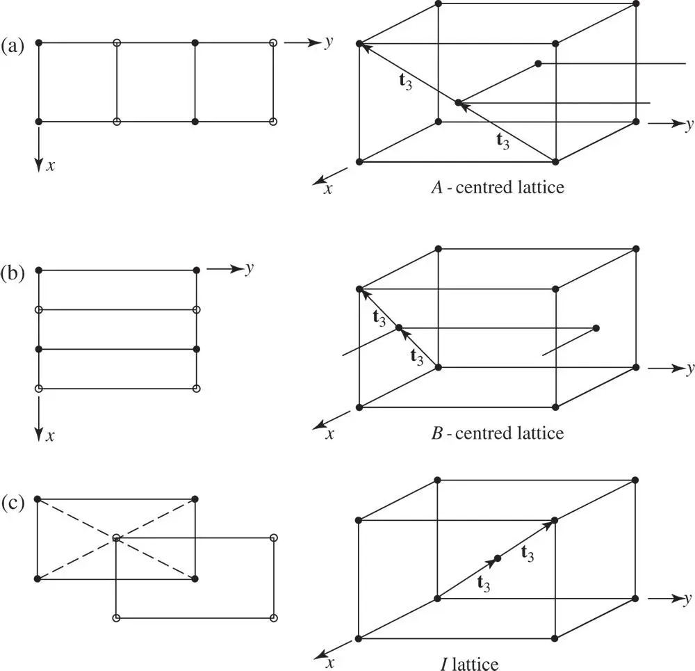
Figure 1.24The three possible stacking sequences of rectangular nets. In the three left‐hand diagrams, lattice points in the net at zero level are denoted with dots and those in the net at level z with open circles. The corresponding three‐dimensional views of the arrangements of the nets are shown in the three right‐hand diagrams
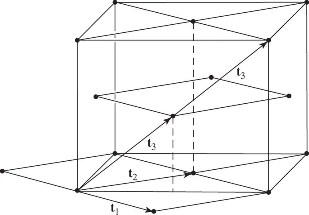
Figure 1.25The staggered stacking of rhombus nets. This form of stacking generates the orthorhombic F Bravais lattice
All of the lattices consistent with 222 – that is, orthorhombic symmetry – are shown in Figures 1.19d, e, f and g. The unit cells are all rectangular parallelepipeds, so that the crystal axes can always be taken at right angles to one another – that is, α = β = γ = 90° – but the cell edges a , b and c may all be different. The primitive lattice P can then be described by a unit cell with lattice points only at the corners, the body‐centred lattice I by a cell with an additional lattice point at its centre and the F lattice by a cell centred on all faces. The A ‐, B ‐ and C ‐centred lattices, shown in Figures 1.24a, 1.24b and 1.23, respectively, are all described by choosing the axes so as to give a cell centred on the (001) face; that is, a C ‐centred cell.
We have so far described nine of the Bravais space lattices. All further lattices are based upon the stacking of triequiangular nets of points. The triequiangular net is shown in Figure 1.14c. There are sixfold axes only at the lattice points of the net. To preserve sixfold rotational symmetry in a three‐dimensional lattice, such nets must be stacked vertically above one another so that t 3is normal to t 1and t 2. The lattice produced has the unit cell shown in Figure 1.19j. The unique hexagonal axis is taken to lie along the z ‐axis so a = b ≠ c , γ = 120° and α and β are both 90°. This lattice (i.e. the array of points) possesses sixfold rotational symmetry and is the only lattice to do so. However, it is also consistent with threefold rotational symmetry about an axis parallel to z . A crystal in which an atomic motif possessing threefold rotational symmetry was associated with each lattice point of this lattice would belong to the trigonal crystal system ( Table 1.3).
Читать дальшеИнтервал:
Закладка:
Похожие книги на «Crystallography and Crystal Defects»
Представляем Вашему вниманию похожие книги на «Crystallography and Crystal Defects» списком для выбора. Мы отобрали схожую по названию и смыслу литературу в надежде предоставить читателям больше вариантов отыскать новые, интересные, ещё непрочитанные произведения.


Обсуждение, отзывы о книге «Crystallography and Crystal Defects» и просто собственные мнения читателей. Оставьте ваши комментарии, напишите, что Вы думаете о произведении, его смысле или главных героях. Укажите что конкретно понравилось, а что нет, и почему Вы так считаете.