Jeremy M. Smallwood - The ESD Control Program Handbook
Здесь есть возможность читать онлайн «Jeremy M. Smallwood - The ESD Control Program Handbook» — ознакомительный отрывок электронной книги совершенно бесплатно, а после прочтения отрывка купить полную версию. В некоторых случаях можно слушать аудио, скачать через торрент в формате fb2 и присутствует краткое содержание. Жанр: unrecognised, на английском языке. Описание произведения, (предисловие) а так же отзывы посетителей доступны на портале библиотеки ЛибКат.

- Название:The ESD Control Program Handbook
- Автор:
- Жанр:
- Год:неизвестен
- ISBN:нет данных
- Рейтинг книги:5 / 5. Голосов: 1
-
Избранное:Добавить в избранное
- Отзывы:
-
Ваша оценка:
The ESD Control Program Handbook: краткое содержание, описание и аннотация
Предлагаем к чтению аннотацию, описание, краткое содержание или предисловие (зависит от того, что написал сам автор книги «The ESD Control Program Handbook»). Если вы не нашли необходимую информацию о книге — напишите в комментариях, мы постараемся отыскать её.
The ESD Control Program Handbook Chapter 6 deals with requirements for compliance given by the IEC 61340-5-1 and ANSI/ESD S20.20 ESD control standards.
Chapter 7 gives an overview of the selection, use, care and maintenance of equipment and furniture commonly used to control ESD risks. The chapter explains how these often work together as part of a system and must be specified with that in mind.
ESD protective packaging is available in an extraordinary range of forms from bags, boxes and bubble wrap to tape and reel packaging for automated processes. The principles and practice of this widely misunderstood area of ESD control are introduced in Chapter 8. The thorny question of how to evaluate an ESD control program is addressed in Chapter 9 with a goal of compliance with a standard as well as effective control of ESD risks and possible customer perceptions.
Whilst evaluating an existing ESD control program provides challenges, developing an ESD control program from scratch provides others. Chapter 10 gives an approach to this.
Standard test methods used in compliance with ESD control standards are explained and simple test procedures given in Chapter 11.
ESD Training has long been recognised as essential in maintaining effective ESD control. Chapter 12 discusses ways of covering essential topics and how to demonstrate static electricity in action. The book ends with a look at where ESD control may go in the near future.
The ESD Control Program Handbook Gives readers a sound understanding of the subject to analyze the ESD control requirements of manufacturing processes, and develop an effective ESD control program Provides practical knowledge, as well as sufficient theory and background to understand the principles of ESD control Teaches how to track and identify how ESD risks arise, and how to identify fitting means for minimizing or eliminating them Emphasizes working with modern ESD control program standards IEC 61340-5-1 and ESD S20:20
is an invaluable reference for anyone tasked with setting up, evaluating, or maintaining an effective ESD control program, training personnel, or making ESD control related measurements. It would form an excellent basis for a University course on the subject as well as a guide and resource for industry professionals.
The ESD Control Program Handbook — читать онлайн ознакомительный отрывок
Ниже представлен текст книги, разбитый по страницам. Система сохранения места последней прочитанной страницы, позволяет с удобством читать онлайн бесплатно книгу «The ESD Control Program Handbook», без необходимости каждый раз заново искать на чём Вы остановились. Поставьте закладку, и сможете в любой момент перейти на страницу, на которой закончили чтение.
Интервал:
Закладка:
The external atmospheric humidity varies daily with the climate and weather, in a range from below 10% rh (cold and dry winter conditions) to 100% rh (fog). The atmospheric relative humidity often has a large effect on material resistance, especially for materials that have resistance above about 1 MΩ. The effective resistance and charge decay times can be reduced over several orders of magnitude with increasing relative humidity for some materials.
Air relative humidity is a strong function of temperature and reduces as temperature increases for a given moisture content. Relative humidity is approximately halved by a 10 °C rise in temperature, if no moisture is added or removed. If, as in winter, cold air is brought indoors and heated, very low relative humidity can result. Hence, ESD problems can be seasonal and occur often in winter. Even in a room where the relative humidity is controlled, dry local microclimates can form where there are heat sources such as equipment, especially if air circulation is restricted.
Table 2.3The effect of humidity on typical electrostatic voltages (MIL HDBK 263).
| Action | Voltage observed | |
| @ 10–20% rh | @ 65–90% rh | |
| Person walking across carpet | 35 000 | 1 500 |
| Person walking across vinyl floor | 12 000 | 250 |
| Person working at bench (not grounded) | 6 000 | 100 |
| Vinyl envelope | 7 000 | 600 |
| Polythene bag picked up from bench | 20 000 | 1 200 |
| Chair padded with polyurethane foam | 18 000 | 15 000 |
A view of the effect of relative humidity on static electricity in daily life is indicated by the following typical voltages ( Table 2.3) given by MIL HDBK 263 as observed at different ambient humidities. These are indicative and cannot be used to predict voltages occurring in real situations.
2.4 Conductors in Electrostatic Fields
2.4.1 Voltage on Conducting and Insulating Bodies and Surfaces
Like charges repel, and in a conductor where charges are free to move rapidly, charge will rapidly move to the outer surface to minimize their proximity to each other. After charge has redistributed, the voltage on all parts of the conductor is equal (equipotential). This must be so – current flows due to voltage differences, until the equipotential state is achieved.
For an insulating object, charge does not flow freely and so the voltage at each point on the surface is typically different from its neighbor. For intermediate materials, the time taken to achieve near equipotential surface is several times the time constant.
For objects that have high resistivity and a long time constant, charge will redistribute to equipotential if we wait long enough (and if the field source is not changing rapidly) – but in the meantime surface voltages can be different.
2.4.2 Electrostatic Field in Practical Situations
For a small point or spherical charge with the balancing charge a long way distant, the strength of the electric field falls off rapidly with distance r , as it is proportional to 1/ r 2. The field line spread out radially ( Figure 2.4). In many practical situations the object presenting an electrostatic field source is too large to be considered a point source.
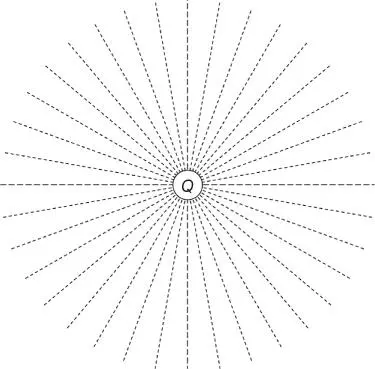
Figure 2.4Field lines (shown dashed) emerging from a small point or spherical charge.
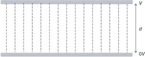
Figure 2.5Electrostatic field between parallel plates.
For larger and different shaped objects, the field line pattern can be very different and the fall‐off in field strength can be much less rapid. In practice, the field lines start and finish on conductors at different voltages in the region, and field lines may be more or less curved at any region in space between them.
The electrostatic field between two large flat parallel plates, well away from the plate edges, is uniform ( Figure 2.5), and the field lines are parallel between the electrodes. Away from the plate edges, the field E is uniform and is easily calculated from the voltage difference between the plates V and the distance between them d .

If a conductor is placed in an electrostatic field, it has the effect of drawing the field to itself with field lines always emerging at right angles to the conductor surface. In response, charges on the conductor are redistributed until the voltage is the same all over the conductor surface. One of the consequences of this is that any instrument we use to measure an electrostatic field inevitably changes the field it is measuring. Figure 2.6shows how this happens with the electrostatic field between a metal plate at voltage V and a grounded electrostatic field meter. The field meter actually sees a field higher than the V / d value. The same effect happens of course for any component, PCB or any other electrostatic discharge–sensitive (ESDS) device brought into the field. The density of the field lines at the surface are related to the field strength and surface charge density induced at the surface. A high concentration of field lines indicates a high field strength.
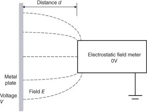
Figure 2.6Electrostatic field between a field meter and metal plate at voltage V .
Field lines tend to congregate at the tip or edge of an object, and the electrostatic field strength becomes more intense in these regions. Discharges tend to occur preferentially from high field strength regions at sharp edges on objects. This is used to an advantage, for example, in using sharp pins to produce intense fields and corona discharges as a source of ions in an ionizer for charge neutralization.
For a charged insulating surface, the situation is even more complicated. A charged insulator will normally have a highly variable charge density over its surface. The surface voltage is highly dependent on the surface charge density and presence of other materials nearby.
2.4.3 Faraday Cage
For a conducting object in an electric field, charge flows until all points on the surface are at the same voltage. This must be so, as any voltage difference would cause a current to flow in the conductor. If the object is hollow, then the field inside the object is zero, because an equipotential conductor surrounds it ( Figure 2.7). An object placed within the hollow conductor would therefore be shielded from the effects of an external field. This hollow conductor is called a Faraday cage .
2.4.4 Induction: An Isolated Conductive Object Attains a Voltage When in an Electric Field
If we consider the behavior of a conductive object as a capacitor, we can quickly understand that the voltage on an isolated conductive object will change under the influence of a nearby charged object and its electric field.
In Figure 2.8an earthed electrostatic field meter is monitoring the voltage V mof a metal plate. There is an effective capacitance C mbetween the metal object and the field meter. The metal object has no net charge and is initially at zero volts.
Читать дальшеИнтервал:
Закладка:
Похожие книги на «The ESD Control Program Handbook»
Представляем Вашему вниманию похожие книги на «The ESD Control Program Handbook» списком для выбора. Мы отобрали схожую по названию и смыслу литературу в надежде предоставить читателям больше вариантов отыскать новые, интересные, ещё непрочитанные произведения.


Обсуждение, отзывы о книге «The ESD Control Program Handbook» и просто собственные мнения читателей. Оставьте ваши комментарии, напишите, что Вы думаете о произведении, его смысле или главных героях. Укажите что конкретно понравилось, а что нет, и почему Вы так считаете.