Allan T. Kirkpatrick - Internal Combustion Engines
Здесь есть возможность читать онлайн «Allan T. Kirkpatrick - Internal Combustion Engines» — ознакомительный отрывок электронной книги совершенно бесплатно, а после прочтения отрывка купить полную версию. В некоторых случаях можно слушать аудио, скачать через торрент в формате fb2 и присутствует краткое содержание. Жанр: unrecognised, на английском языке. Описание произведения, (предисловие) а так же отзывы посетителей доступны на портале библиотеки ЛибКат.
- Название:Internal Combustion Engines
- Автор:
- Жанр:
- Год:неизвестен
- ISBN:нет данных
- Рейтинг книги:5 / 5. Голосов: 1
-
Избранное:Добавить в избранное
- Отзывы:
-
Ваша оценка:
Internal Combustion Engines: краткое содержание, описание и аннотация
Предлагаем к чтению аннотацию, описание, краткое содержание или предисловие (зависит от того, что написал сам автор книги «Internal Combustion Engines»). Если вы не нашли необходимую информацию о книге — напишите в комментариях, мы постараемся отыскать её.
New engine technologies and concepts Effects of engine speed on performance and emissions Fluid mechanics of intake and exhaust flow in engines Turbocharger and supercharger performance analysis Chemical kinetic modeling, reaction mechanisms, and emissions Advanced combustion processes including low temperature combustion Piston, ring and journal bearing friction analysis The
expands on the combined analytical and numerical approaches used successfully in previous editions. Students and engineers are provided with several new tools for applying the fundamental principles of thermodynamics, fluid mechanics, and heat transfer to internal combustion engines.
Each chapter includes MATLAB programs and examples showing how to perform detailed engineering computations. The chapters also have an increased number of homework problems with which the reader can gauge their progress and retention. All the software is ‘open source’ so that readers can see in detail how computational analysis and the design of engines is performed. A companion website is also provided, offering access to the MATLAB computer programs.
Internal Combustion Engines — читать онлайн ознакомительный отрывок
Ниже представлен текст книги, разбитый по страницам. Система сохранения места последней прочитанной страницы, позволяет с удобством читать онлайн бесплатно книгу «Internal Combustion Engines», без необходимости каждый раз заново искать на чём Вы остановились. Поставьте закладку, и сможете в любой момент перейти на страницу, на которой закончили чтение.
Интервал:
Закладка:
Revolutionary changes have taken place with engine controls and fuel delivery systems in recent years and the progress continues. The ignition and fuel injection systems of the engine are now controlled by computers. Conventional carburetors in automobiles were replaced by throttle body fuel injectors in the 1980s, which in turn were replaced by port fuel injectors in the 1990s. Port fuel injectors are located in the intake port of each cylinder just upstream of the intake valve, so there is an injector for each cylinder. The port injector does not need to maintain a continuous fuel spray, since the time lag for fuel delivery is much less than that of a throttle body injector.
Direct injection spark‐ignition engines are available on many production engines. With direct injection, the fuel is sprayed directly into the cylinder during the late stages of the compression stroke. Compared with port injection, direct injection engines can be operated at a higher compression ratio, and therefore will have a higher theoretical efficiency, since the combustion knock limitations are reduced. They can also be unthrottled, resulting in a greater volumetric efficiency at part load. The evaporation of the injected fuel in the combustion chamber will have a charge cooling effect, which will also increase volumetric efficiency.
Cooling Systems
Some type of cooling system is required to remove the approximately 30% of the fuel energy rejected as waste heat. Liquid and air cooling are the two main types of cooling systems. The liquid cooling system (see Figure 1.17) is usually a single loop where a water pump sends coolant to the engine block, and then to the head. Warm coolant flows through the intake manifold to warm it and thereby assist in vaporizing the fuel. The coolant will then flow to a radiator or heat exchanger, reject the waste heat to the atmosphere, and flow back to the pump. When the engine is cold, a thermostat prevents coolant from returning to the radiator, resulting in a more rapid warmup of the engine. Liquid‐cooled engines are quieter than air‐cooled engines, but have leaking, boiling, and freezing problems. Engines with relatively low power output, less than 20 kW, primarily use air cooling. Air‐cooling systems use fins to lower the air side surface temperature (see Figure 1.18). There are historical examples of combined water and air cooling. The Mors, an early 1920s automobile, had a finned air‐cooled cylinder and water‐cooled heads.
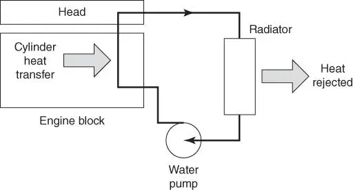
Figure 1.17Liquid cooling system schematic.
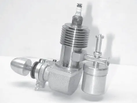
Figure 1.18Air cooling of model airplane engine. (Courtesy R. Schroeder.)
1.6 Examples of Internal Combustion Engines
Automotive Spark‐Ignition Four‐Stroke Engine
A photograph of a V‐6 3.2 L automobile engine is shown as in Figure 1.19and in cutaway view in Figure 1.20. The engine has a 89 mm bore and a stroke of 86 mm. The maximum power is 165 kW (225 hp) at 5550 rpm. The engine has a single overhead camshaft per piston bank with four valves per cylinder. The pistons are flat with notches for valve clearance. The fuel is mixed with the inlet air by spraying the fuel into the intake port at the Y‐junction just above the intake valves.
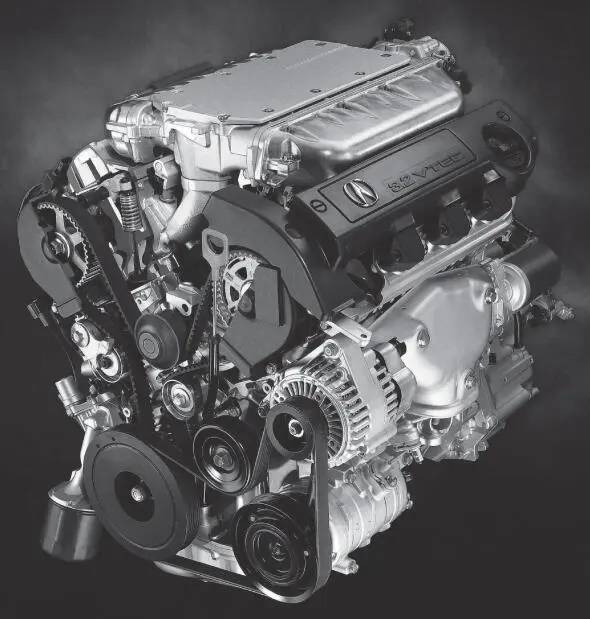
Figure 1.193.2 L V‐6 automobile engine. (Courtesy of Honda Motor Co.)
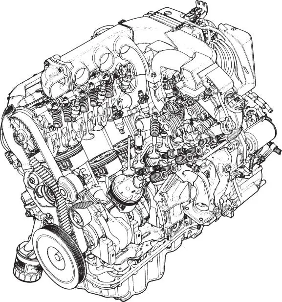
Figure 1.20Cutaway view of 3.2 L V‐6 automobile engine. (Courtesy of Honda Motor Co.)
As shown in Figure 1.21, the overhead camshaft acts on both the intake and exhaust valves via rocker arms. The engine has variable valve timing applied to the intake valves with a shift from low‐lift short duration cam lobes to high‐lift long duration cam lobes above 3500 rpm. In the low‐lift short duration cam operation the two intake valves have staggered timing, which creates additional swirl to increase flame propagation and combustion stability. Roller bearings are used on the rocker arms to reduce friction. The clearance volume is formed by an angled pent roof in the cylinder head, with the valves also angled.
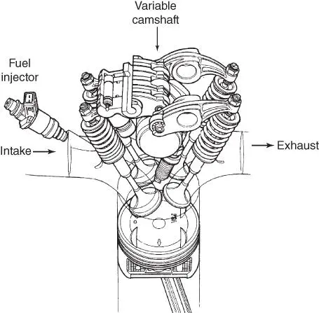
Figure 1.21A variable valve timing mechanism. (Courtesy of Honda Motor Co.)
Heavy‐Duty Truck Diesel Engine
A heavy‐duty truck diesel engine is shown in Figures 1.22. This engine is an inline six‐cylinder turbocharged diesel engine with a 137‐mm bore and 165‐mm stroke for a total displacement of 14.6 L. The rated engine power is 373 kW (500 hp). The compression ratio is 16.5 to 1. The engine has electronically controlled, mechanically actuated fuel injectors, and an overhead camshaft. Note that the cylinder head is flat, with the diesel fuel injector mounted in the center of the combustion chamber. The inlet ports impart a swirl to the air in the combustion chamber to improve mixing with the radial fuel spray.
The top of the piston has a torus‐shaped crater bowl, so that the initial combustion will take place in the piston bowl. The injection nozzles have three to six holes through which the fuel sprays into the piston bowl. The pressure required to spray the diesel fuel into the combustion chamber is of the order of 1000 bar, for adequate spray penetration into the bowl and subsequent atomization of the diesel fuel. The fuel injection pressure is generated by a plunger driven by the camshaft rocker arm.
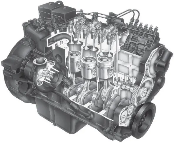
Figure 1.22A 5.9 L L6 on‐highway diesel engine. (Courtesy of PriceWebber.)
Stationary Gas Engine
A stationary natural gas engine is shown in Figures 1.23and 1.24. Typical applications for stationary engines include co‐generation, powering gas compressors, and power generation. The engine shown in Figure 1.23is an in‐line eight‐cylinder turbocharged engine, with rated power of 1200 kW, bore of 240 mm, and stroke of 260 mm for a total displacement of 94 L. The compression ratio is 10.9:1. This type of engine is designed to operate at a constant speed condition, typically 1200 rpm. Each cylinder has two intake and two exhaust valves. The piston has a combustion bowl with a deep dish concentrated near the center of the piston, so most of the clearance volume is in the piston bowl.
Since natural gas engines are operated lean to reduce nitrogen oxides (  ), prechambers are used to initiate a stable combustion process. Pressurized natural gas is injected into a prechamber above the piston, and a spark plug in the prechamber is used to ignite the natural gas. The increase in pressure projects the burning mixture into the main combustion chamber, where the final stages of the combustion take place. Prechambers are also used in high‐speed diesel engines to achieve acceptable mixing and more complete combustion.
Интервал:
Закладка:
Похожие книги на «Internal Combustion Engines»
Представляем Вашему вниманию похожие книги на «Internal Combustion Engines» списком для выбора. Мы отобрали схожую по названию и смыслу литературу в надежде предоставить читателям больше вариантов отыскать новые, интересные, ещё непрочитанные произведения.


Обсуждение, отзывы о книге «Internal Combustion Engines» и просто собственные мнения читателей. Оставьте ваши комментарии, напишите, что Вы думаете о произведении, его смысле или главных героях. Укажите что конкретно понравилось, а что нет, и почему Вы так считаете.