Allan T. Kirkpatrick - Internal Combustion Engines
Здесь есть возможность читать онлайн «Allan T. Kirkpatrick - Internal Combustion Engines» — ознакомительный отрывок электронной книги совершенно бесплатно, а после прочтения отрывка купить полную версию. В некоторых случаях можно слушать аудио, скачать через торрент в формате fb2 и присутствует краткое содержание. Жанр: unrecognised, на английском языке. Описание произведения, (предисловие) а так же отзывы посетителей доступны на портале библиотеки ЛибКат.
- Название:Internal Combustion Engines
- Автор:
- Жанр:
- Год:неизвестен
- ISBN:нет данных
- Рейтинг книги:5 / 5. Голосов: 1
-
Избранное:Добавить в избранное
- Отзывы:
-
Ваша оценка:
Internal Combustion Engines: краткое содержание, описание и аннотация
Предлагаем к чтению аннотацию, описание, краткое содержание или предисловие (зависит от того, что написал сам автор книги «Internal Combustion Engines»). Если вы не нашли необходимую информацию о книге — напишите в комментариях, мы постараемся отыскать её.
New engine technologies and concepts Effects of engine speed on performance and emissions Fluid mechanics of intake and exhaust flow in engines Turbocharger and supercharger performance analysis Chemical kinetic modeling, reaction mechanisms, and emissions Advanced combustion processes including low temperature combustion Piston, ring and journal bearing friction analysis The
expands on the combined analytical and numerical approaches used successfully in previous editions. Students and engineers are provided with several new tools for applying the fundamental principles of thermodynamics, fluid mechanics, and heat transfer to internal combustion engines.
Each chapter includes MATLAB programs and examples showing how to perform detailed engineering computations. The chapters also have an increased number of homework problems with which the reader can gauge their progress and retention. All the software is ‘open source’ so that readers can see in detail how computational analysis and the design of engines is performed. A companion website is also provided, offering access to the MATLAB computer programs.
Internal Combustion Engines — читать онлайн ознакомительный отрывок
Ниже представлен текст книги, разбитый по страницам. Система сохранения места последней прочитанной страницы, позволяет с удобством читать онлайн бесплатно книгу «Internal Combustion Engines», без необходимости каждый раз заново искать на чём Вы остановились. Поставьте закладку, и сможете в любой момент перейти на страницу, на которой закончили чтение.
Интервал:
Закладка:
Since material stresses in an engine depend to a first order only on the bmep and mean piston speed, it follows that for the same stress limit imposed by the material, all engines should have the same bmep and mean piston speed. Finally, since the engines geometrically resemble one another independent of size, the mass per unit displacement volume is more or less independent of engine size.
1.5 Engine Configurations
Internal combustion engines can be built in many different configurations. For a given engine, using a four‐ or two‐stroke Otto or Diesel cycle, the configurations are characterized by the piston‐cylinder geometry, the inlet and exhaust valve geometry, the use of super or turbochargers, the type of fuel delivery system, and the type of cooling system. The reciprocating piston‐cylinder combination remains the dominant configuration of the internal combustion engine.
Since the invention of the internal combustion engine, many different piston‐cylinder geometries have been designed, as shown in Figure 1.13. The choice of a given arrangement depends on a number of factors and constraints, such as engine balancing and available volume. The in‐line engine is the most prevalent because it is the simplest to manufacture and maintain. The V engine is formed from two in‐line banks of cylinders set at an angle to each other, forming the letter V. A horizontally opposed or flat engine is a V engine with 180  offset piston banks. The W engine is formed from three in‐line banks of cylinders set at an angle to each other, forming the letter W. A radial engine has all of the cylinders in one plane with equal spacing between cylinder axes. Radial engines are used in air‐cooled aircraft applications since each cylinder can be cooled equally. Since the cylinders are in a plane, a master connecting rod is used for one cylinder, and articulated rods are attached to the master rod. Alternatives to the reciprocating piston‐cylinder arrangement have also been developed, such as the rotary Wankel engine, in which a triangular shaped rotor rotates eccentrically in a housing to achieve compression, ignition, and expansion of a fuel–air mixture.
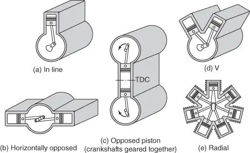
Figure 1.13Various piston‐cylinder geometries. (Adapted from Obert 1950.)
Intake and Exhaust Valve Arrangement
Gases are admitted and expelled from the cylinders by valves that open and close at the proper times, or by ports that are uncovered or covered by the piston. There are many design variations for the intake and exhaust valve type and location. Poppet valves (see Figure 1.14) are the primary valve type used in internal combustion engines since they have excellent sealing characteristics. As shown in the pushrod configuration of Figure 1.14, springs are used to return the valve to a closed position. Sleeve and rotary valves have also been used, but do not seal the combustion chamber as well as poppet valves.
The poppet valves can be located either in the engine block or in the cylinder head, depending on airflow, cooling, and manufacturing considerations. Older engines and small four‐stroke engines have the inlet and exhaust valves located in the block parallel to the cylinders, a configuration termed under‐head or L‐head. This configuration provides good cooling to the valves from the engine block coolant, however with undersquare (bore  stroke) engines the maximum valve diameter is limited, resulting in poor volumetric efficiency. The F‐head configuration positions the intake valve in the cylinder head just above the cylinder, increasing the volumetric efficiency, with the exhaust valve remaining on the side.
Currently, most engines use valves located in the cylinder head, an overhead or I‐head configuration, as this configuration has allows increased valve diameter resulting in good inlet and exhaust flow characteristics. However, overhead valves are more difficult to cool than L‐head valves.

Figure 1.14Poppet valve assembly. (Adapted from Taylor 1985.)
The valve timing is controlled by a camshaft that rotates at half the engine speed for a four‐stroke engine. Lobes on the camshaft along with lifters, pushrods, and rocker arms control the valve motion. The inlet valves in early (circa 1910) engines were spring loaded, and were opened during the inlet stroke by the atmosphere‐cylinder pressure differential. Most automotive engines currently use an overhead camshaft to eliminate pushrods and simplify the valve train.
A valve timing profile is shown in Figure 1.15. The valve opening and closing angles are not necessarily symmetric about top and bottom dead center, due to fluid flow considerations discussed in Chapter 05. The valve timing can be varied to increase volumetric efficiency through the use of advanced camshafts that have moveable lobes, or with electric valves. With a change in the load and speed, the valve opening duration and timing can be adjusted to optimize power and/or efficiency.
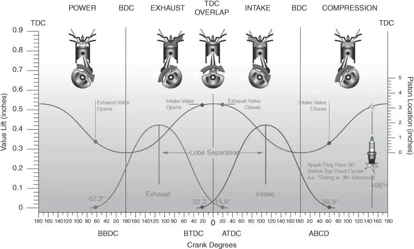
Figure 1.15Poppet valve timing profile. (Courtesy of Competition Cams, Inc.)
Superchargers and Turbochargers
All the engines discussed so far are naturally aspirated, i.e., as the intake gas is drawn in by the downward motion of the piston. Engines can also be supercharged or turbocharged. Supercharging is mechanical compression of the inlet air to a pressure higher than standard atmosphere by a compressor powered by the crankshaft. The compressor increases the density of the intake air so that more fuel and air can be delivered to the cylinder to increase the power. The concept of turbocharging is illustrated in Figure 1.16. Exhaust gas leaving an engine is further expanded through a turbine that drives a compressor. The benefits are twofold: (1) the engine is more efficient because energy that would have otherwise been wasted is recovered from the exhaust gas; and (2) a smaller engine can be constructed to produce a given power because it is more efficient and because the density of the incoming charge is greater. The power available to drive the compressor when turbocharging is a nonlinear function of engine speed such that at low speeds there is little, if any, boost (density increase), whereas at high speeds the boost is maximum. It is also low at part throttle and high at wide‐open throttle. These are desirable characteristics for an automotive engine since throttling or pumping losses are minimized. Most large and medium‐size diesel engines are turbocharged to increase their efficiency. With the anticipated adoption of 48V electrical systems in vehicles, there will be increased use of electrically powered superchargers used in conjunction with a turbocharger to reduce ”turbo lag.”
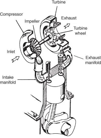
Figure 1.16Turbocharger schematic. (Courtesy of Schwitzer.)
Fuel Injectors and Carburetors
Интервал:
Закладка:
Похожие книги на «Internal Combustion Engines»
Представляем Вашему вниманию похожие книги на «Internal Combustion Engines» списком для выбора. Мы отобрали схожую по названию и смыслу литературу в надежде предоставить читателям больше вариантов отыскать новые, интересные, ещё непрочитанные произведения.


Обсуждение, отзывы о книге «Internal Combustion Engines» и просто собственные мнения читателей. Оставьте ваши комментарии, напишите, что Вы думаете о произведении, его смысле или главных героях. Укажите что конкретно понравилось, а что нет, и почему Вы так считаете.