Marvin Rausand - System Reliability Theory
Здесь есть возможность читать онлайн «Marvin Rausand - System Reliability Theory» — ознакомительный отрывок электронной книги совершенно бесплатно, а после прочтения отрывка купить полную версию. В некоторых случаях можно слушать аудио, скачать через торрент в формате fb2 и присутствует краткое содержание. Жанр: unrecognised, на английском языке. Описание произведения, (предисловие) а так же отзывы посетителей доступны на портале библиотеки ЛибКат.
- Название:System Reliability Theory
- Автор:
- Жанр:
- Год:неизвестен
- ISBN:нет данных
- Рейтинг книги:3 / 5. Голосов: 1
-
Избранное:Добавить в избранное
- Отзывы:
-
Ваша оценка:
System Reliability Theory: краткое содержание, описание и аннотация
Предлагаем к чтению аннотацию, описание, краткое содержание или предисловие (зависит от того, что написал сам автор книги «System Reliability Theory»). Если вы не нашли необходимую информацию о книге — напишите в комментариях, мы постараемся отыскать её.
· The main system reliability assessment methods
· Common-cause failure modeling
· Deterioration modeling
· Maintenance modeling and assessment using Python code
· Bayesian probability and methods
· Life data analysis using R
Perfect for undergraduate and graduate students taking courses in reliability engineering, this book also serves as a reference and resource for practicing statisticians and engineers.
Throughout, the book has a practical focus, incorporating industry feedback and real-world industry problems and examples.
System Reliability Theory — читать онлайн ознакомительный отрывок
Ниже представлен текст книги, разбитый по страницам. Система сохранения места последней прочитанной страницы, позволяет с удобством читать онлайн бесплатно книгу «System Reliability Theory», без необходимости каждый раз заново искать на чём Вы остановились. Поставьте закладку, и сможете в любой момент перейти на страницу, на которой закончили чтение.
Интервал:
Закладка:
System Structure
The RBD is not a physical layout diagram of the system, but a logic diagram that shows how and when the system function, SF, is up. The sequence of failures is not important, and the RBD in Figure 2.10is therefore equivalent to the RBD in Figure 2.11. The RBD shows the structure of the system with respect to a specified system function, SF. When discussing RBD, we talk about the structure instead of the system. Separate RBDs have to be established for each system function.
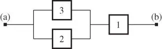
Figure 2.11An alternative, and identical, version of the RBD in Figure 2.10.
Boolean Representation
Arranging several components along a path means connecting them by an AND‐ operation and arranging several components in parallel paths represents and OR‐operation. In essence, a RBD is a graphical representation of a Boolean expression . Boolean expressions are discussed further in Section 4.6. The system function SF in Figure 2.10is seen to be up if block 1 is up AND block 2 OR block 3 is up.
2.8.2 Series Structure
A series structure is functioning if and only if all the  blocks are functioning. This means that the structure fails as soon as one block fails. The RBD of a series structure of
  blocks is shown in Figure 2.12. A path is seen to be available between the end points (a) and (b) – and the system is functioning – if and only if all the
  blocks are functioning. The system function can be represented by the Boolean expression: The series structure is functioning if block 1 AND block 2 AND
  AND block
  are all functioning. As mentioned above, the sequence of the blocks in Figure 2.12is not important, and we might have drawn the RBD with the
  blocks in any sequence.
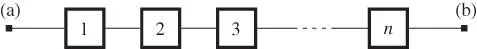
Figure 2.12RBD for a series structure.
2.8.3 Parallel Structure
A parallel structure is functioning as long as at least one of its  blocks is able to function. The RBD of a parallel structure is shown in Figure 2.13. For this structure, there are
  different paths between the end points (a) and (b). The structure is functioning if any one of these
  paths is functioning. This means that the structure is functioning if at least one of the
  blocks is functioning. The parallel structure can be represented by the Boolean expression: The parallel structure is functioning if block 1 OR block 2
  OR block
  is functioning.
Figure 2.13Parallel structure.
2.8.4 Redundancy
Redundancy is a means to improve the reliability of a structure. Redundancy may be defined as follows:
Definition 2.9 (Redundancy)
The provision of more than one means or parallel paths in a structure for performing a given function such that all means must fail before causing system failure.
The parallel structure in Figure 2.13has redundancy because all the  blocks have to fail to cause the specified system failure, SF. Because
  blocks have to fail, the system is said to have redundancy of order
  .
.
Parallel or redundant paths can be installed for a single block, for a selection of blocks, or for the entire system function, SF.
For hardware, redundancy may be achieved by installing one or more extra hardware items in parallel with the initial item. The redundant items may be identical or diverse. Adding redundancy increases the cost and makes the system more complicated, but if the cost of failure is high, redundancy is often an attractive option.
2.8.5 Voted Structure
A  ‐out‐of‐
  (
(  oo
oo  ) voted structure is functioning as long as at least
  of its
  blocks are functioning (
  ). Observe that an
  oo
oo  voted structure is a series structure and a 1oo
  structure is a parallel structure.
A 2oo3 voted structure is shown in Figure 2.14. Two different diagrams are shown. The diagram to the left is a physical diagram that shows the 2oo3 logic, whereas the RBD to the right is a series–parallel structure. In the RBD, we see that the system is functioning when block 1 AND block 2 are functioning OR block 1 AND block 3 are functioning OR block 2 AND block 3 are functioning. Observe that each block appears in two different places in this RBD. This shows that an RBD is not a physical layout diagram, but a logical graph illustrating the specified function of the system.
Читать дальшеИнтервал:
Закладка:
Похожие книги на «System Reliability Theory»
Представляем Вашему вниманию похожие книги на «System Reliability Theory» списком для выбора. Мы отобрали схожую по названию и смыслу литературу в надежде предоставить читателям больше вариантов отыскать новые, интересные, ещё непрочитанные произведения.


Обсуждение, отзывы о книге «System Reliability Theory» и просто собственные мнения читателей. Оставьте ваши комментарии, напишите, что Вы думаете о произведении, его смысле или главных героях. Укажите что конкретно понравилось, а что нет, и почему Вы так считаете.