Marvin Rausand - System Reliability Theory
Здесь есть возможность читать онлайн «Marvin Rausand - System Reliability Theory» — ознакомительный отрывок электронной книги совершенно бесплатно, а после прочтения отрывка купить полную версию. В некоторых случаях можно слушать аудио, скачать через торрент в формате fb2 и присутствует краткое содержание. Жанр: unrecognised, на английском языке. Описание произведения, (предисловие) а так же отзывы посетителей доступны на портале библиотеки ЛибКат.
- Название:System Reliability Theory
- Автор:
- Жанр:
- Год:неизвестен
- ISBN:нет данных
- Рейтинг книги:3 / 5. Голосов: 1
-
Избранное:Добавить в избранное
- Отзывы:
-
Ваша оценка:
System Reliability Theory: краткое содержание, описание и аннотация
Предлагаем к чтению аннотацию, описание, краткое содержание или предисловие (зависит от того, что написал сам автор книги «System Reliability Theory»). Если вы не нашли необходимую информацию о книге — напишите в комментариях, мы постараемся отыскать её.
· The main system reliability assessment methods
· Common-cause failure modeling
· Deterioration modeling
· Maintenance modeling and assessment using Python code
· Bayesian probability and methods
· Life data analysis using R
Perfect for undergraduate and graduate students taking courses in reliability engineering, this book also serves as a reference and resource for practicing statisticians and engineers.
Throughout, the book has a practical focus, incorporating industry feedback and real-world industry problems and examples.
System Reliability Theory — читать онлайн ознакомительный отрывок
Ниже представлен текст книги, разбитый по страницам. Система сохранения места последней прочитанной страницы, позволяет с удобством читать онлайн бесплатно книгу «System Reliability Theory», без необходимости каждый раз заново искать на чём Вы остановились. Поставьте закладку, и сможете в любой момент перейти на страницу, на которой закончили чтение.
Интервал:
Закладка:
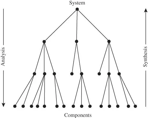
Figure 2.7System analysis and synthesis.
An emergent property is a system property that cannot be deduced from the properties of the system components. In many cases, emergent properties lead to unexpected system behavior that may be dangerous. A system is usually not designed or built to be complex, but may develop into a complex system through changes, coupling, and emergence.
There is a considerable disagreement about how to delimit the concept of emergence. Some authors interpret emergence very widely and say that “properties” such as reliability, quality, and safety are emergent properties of a system.
Simple and complicated systems can be studied based on the Newtonian–Cartesian paradigm, whereas complex systems cannot be adequately studied within this paradigm. A new worldview called the complexity paradigm is therefore being developed.
All the examples in this book are related to simple systems, but the theory and methods presented may also be applied to complicated systems and many aspects of complex systems. Complex systems as such are not studied in this book.
Remark 2.1 (Classical methods  waste of time?)
Finally, you may wonder if the effort you make to learn the theory and methods described in this book is a waste of time when your study object is complex. According to Einstein and Infeld (1938), the development of new theory may be compared with climbing a mountain. When you have come to a certain height, you get a better overview, but you may realize that you need another strategy to reach the summit. To have reached the present height is an achievement that gives a good understanding of the further climbing efforts.
2.8 System Structure Modeling
An early step of a system reliability study is to establish a model of the system structure. The model defines the system boundary and the elements of the system (i.e. inside the system boundary) and the interactions between these elements. We also make assumptions about how the system is operated and the environmental conditions and constraints that may affect the system elements and their behavior. A range of system modeling techniques are presented in later chapters. Here, we delimit the presentation to a rather simple approach – reliability block diagrams.
2.8.1 Reliability Block Diagram
This section describes how a system function (SF) can be modeled by a reliability block diagram (RBD). An RBD is a success‐oriented graph with a single source (a) and a single terminal (b). The nodes of the RBD are called blocks or functional blocks . Each block represents a component function (or a combination of two or more functions). We assume that the blocks are numbered  , where
  is known. This numbering is for convenience. In practical applications, a combination of letters and digits are often used to identify component functions. An RBD with
  blocks is called an RBD of order
  .
.
Each block is either functioning or failed , but the terms up and down are also used. Intermediate states are not allowed. To block  (for
(for 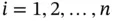 ) is connected a binary state variable
  , defined as follows:
(2.1) 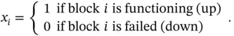
Observe that  means that the specified function of block
  is up. It does not mean that all the functions of the component associated with block
  are up.
Blocks are drawn as squares or rectangles, as shown is Figure 2.8for component function  . Connection between the end points (a) and (b) in Figure 2.8means that block
  is functioning (i.e.
  ). It is possible to enter more information into the block and include a brief description of the required component function. An example is shown in Figure 2.9, where the component is a safety shutdown valve that is installed in a pipeline. A label is used to identify the block.
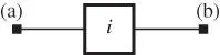
Figure 2.8Component function  shown as a block.
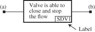
Figure 2.9Alternative representation of the block in Figure 2.8
An RBD with three blocks representing a system function, SF, is shown in Figure 2.10. The system function, SF, is up if block 1 is functioning and either block 2, block 3, or both are functioning.
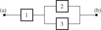
Figure 2.10A simple reliability block diagram with three blocks.
The blocks in Figure 2.10are connected by arcs . Arcs are also called edges . The arcs are not directed, but directed arcs may sometimes be used to clarify the logic of the diagram. The system function, SF, is up if there exists a path from (a) to (b) through functioning blocks, otherwise, it is down. The RBD in Figure 2.10is seen to have two paths  and
and  .
.
Интервал:
Закладка:
Похожие книги на «System Reliability Theory»
Представляем Вашему вниманию похожие книги на «System Reliability Theory» списком для выбора. Мы отобрали схожую по названию и смыслу литературу в надежде предоставить читателям больше вариантов отыскать новые, интересные, ещё непрочитанные произведения.


Обсуждение, отзывы о книге «System Reliability Theory» и просто собственные мнения читателей. Оставьте ваши комментарии, напишите, что Вы думаете о произведении, его смысле или главных героях. Укажите что конкретно понравилось, а что нет, и почему Вы так считаете.