Marvin Rausand - System Reliability Theory
Здесь есть возможность читать онлайн «Marvin Rausand - System Reliability Theory» — ознакомительный отрывок электронной книги совершенно бесплатно, а после прочтения отрывка купить полную версию. В некоторых случаях можно слушать аудио, скачать через торрент в формате fb2 и присутствует краткое содержание. Жанр: unrecognised, на английском языке. Описание произведения, (предисловие) а так же отзывы посетителей доступны на портале библиотеки ЛибКат.
- Название:System Reliability Theory
- Автор:
- Жанр:
- Год:неизвестен
- ISBN:нет данных
- Рейтинг книги:3 / 5. Голосов: 1
-
Избранное:Добавить в избранное
- Отзывы:
-
Ваша оценка:
System Reliability Theory: краткое содержание, описание и аннотация
Предлагаем к чтению аннотацию, описание, краткое содержание или предисловие (зависит от того, что написал сам автор книги «System Reliability Theory»). Если вы не нашли необходимую информацию о книге — напишите в комментариях, мы постараемся отыскать её.
· The main system reliability assessment methods
· Common-cause failure modeling
· Deterioration modeling
· Maintenance modeling and assessment using Python code
· Bayesian probability and methods
· Life data analysis using R
Perfect for undergraduate and graduate students taking courses in reliability engineering, this book also serves as a reference and resource for practicing statisticians and engineers.
Throughout, the book has a practical focus, incorporating industry feedback and real-world industry problems and examples.
System Reliability Theory — читать онлайн ознакомительный отрывок
Ниже представлен текст книги, разбитый по страницам. Система сохранения места последней прочитанной страницы, позволяет с удобством читать онлайн бесплатно книгу «System Reliability Theory», без необходимости каждый раз заново искать на чём Вы остановились. Поставьте закладку, и сможете в любой момент перейти на страницу, на которой закончили чтение.
Интервал:
Закладка:
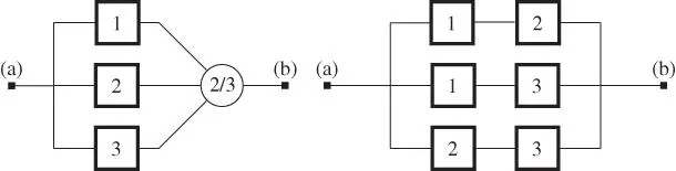
Figure 2.14Voted structure 2oo3, (left) a physical diagram and (right) an RBD.
2.8.6 Standby Structure
Redundancy may either be active , in which case the redundant items operate simultaneously in performing the same function (as for the parallel structure), or standby , such that the redundant items are only activated when the primary item fails. With standby redundancy, the standby items may be in cold standby or in partly loaded standby. With cold standby, the redundant item is considered to be as‐good‐as‐new when activated. With partly loaded standby, the item may be failed or worn when activated.
A simple standby structure with two blocks is shown in Figure 2.15. Initially, block 1 is functioning. When block 1 fails, a signal is sent to the switch  to activate block 2 and a repair action of block 1 may be started. The switch
  may be automatic, or a manual action to connect and start block 2. Depending on the operating rules, block 1 may be activated again as soon as the repair action is completed, or block 2 may run until it fails.
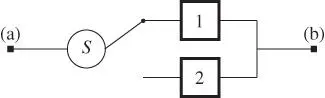
Figure 2.15Standby structure.
2.8.7 More Complicated Structures
Many of the structures, we study in this book, can be represented by a series–parallel RBD. A simple example of such a structure is shown in Figure 2.16.
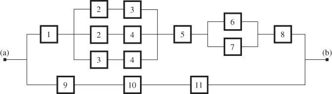
Figure 2.16RBD for a series–parallel structure.
Remark 2.2 (Series–parallel structures)
The term series–parallel structure is not used in the same way by all authors. Some authors use the term to describe a series structure, where one or more of the blocks have added redundancy, that is, have parallel paths. The same authors use the term “parallel‐series structure” to describe a parallel structure where two or more blocks appear in at least one of the parallel paths. In this book, we use the term series–parallel structure to describe a structure, where the blocks are arranged in any combination of series and parallel structures (as indicated in Figure 2.16).
2.8.8 Two Different System Functions
The fact that different system functions give rise to different RBDs is illustrated in Example 2.2.
Example 2.2 (Pipeline with safety valves)
Consider a pipeline with two independent safety valves  and
and  that are physically installed in series, as shown in Figure 2.17a. The valves are supplied with a spring loaded fail‐safe‐close hydraulic actuator. The valves are opened and held open by hydraulic pressure and is closed automatically by spring force whenever the hydraulic pressure is removed or lost. In normal operation, both valves are held open. The essential function of the valve system is to act as a safety barrier, that is, to close and “stop flow” in the pipeline in case of an emergency.
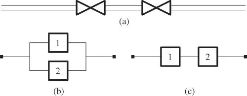
Figure 2.17Two safety valves in a pipeline: (a) physical layout, (b) RBD for the safety barrier function, and (c) RBD for spurious closure.
The two blocks in Figure 2.17b represent the valve function “stop flow” for valve 1 and 2, respectively. This means that each valve is able to close and stop the flow in the pipeline. To achieve the system function “stop flow,” it is sufficient that at least one of the individual valves can “stop flow.” The associated RBD is therefore a parallel structure with respect to the system function “stop flow.”
The valves may close spuriously, that is, without a control signal, and stop the flow in the pipeline. The two blocks in Figure 2.17c represent the valve function “maintain flow” in the pipeline, for valves 1 and 2, respectively. Because the flow in the pipeline stops when one of the valves closes, the system function “maintain flow” is fulfilled only when both valves function with respect to the valve function “maintain flow”. The associated RBD is therefore a series structure for the system function “maintain flow.”
Example 2.2shows that two different functions of a single system give rise to two different RBD. Observe also that the blocks in the two RBDs represent different component functions in (b) and (c).
Remark 2.3 (Terminology problem)
Many authors use the term “component” instead of block. There is nothing wrong with this terminology–and we also use it later in this book–but we have to be very careful when, for example, saying that “component  is functioning.” In cases, when it is not fully obvious, we should always add “with respect to the specified function.”
2.8.9 Practical Construction of RBDs
A specific system function, SF, usually requires a long range of subfunctions. For the essential function of a car, for example, we need the functions of the engine, the brakes, the steering, the ventilation, and many more. The RBD for the SF is then a long series structure of the required subsystem functions, as shown in Figure 2.18. Each of the required subfunctions may again need sub‐subfunctions.
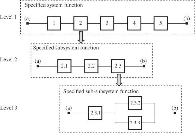
Figure 2.18Construction of the RBD in levels.
How many levels are required to depend on how complicated the system function is and the objectives of the analysis. RBDs are further discussed in Chapter 4. Chapter 6 deals with quantitative reliability analysis based on RBDs.
2.9 Problems
1 2.1 Identify and describe briefly the main subsystems of a family car and establish a system breakdown structure for the car.
2 2.2 Establish a function tree for a (domestic) refrigerator.
3 2.3 List the environmental, operating, and maintenance factors that should be considered when defining the operating context of a family car.
4 2.4 List some information functions that are available in a modern car.
5 2.5 Identify the main functions of a family car and establish a function tree for the car.
6 2.6 List some safety functions of a modern car. Are the identified functions online or offline functions?
7 2.7 Identify and describe the functions of the front door of a house.
8 2.8 Describe the functions of a vacuum flask (thermos) and suggest relevant performance criteria.
9 2.9 Describe briefly a system you consider to be complex.
Читать дальшеИнтервал:
Закладка:
Похожие книги на «System Reliability Theory»
Представляем Вашему вниманию похожие книги на «System Reliability Theory» списком для выбора. Мы отобрали схожую по названию и смыслу литературу в надежде предоставить читателям больше вариантов отыскать новые, интересные, ещё непрочитанные произведения.


Обсуждение, отзывы о книге «System Reliability Theory» и просто собственные мнения читателей. Оставьте ваши комментарии, напишите, что Вы думаете о произведении, его смысле или главных героях. Укажите что конкретно понравилось, а что нет, и почему Вы так считаете.