Position, Navigation, and Timing Technologies in the 21st Century
Здесь есть возможность читать онлайн «Position, Navigation, and Timing Technologies in the 21st Century» — ознакомительный отрывок электронной книги совершенно бесплатно, а после прочтения отрывка купить полную версию. В некоторых случаях можно слушать аудио, скачать через торрент в формате fb2 и присутствует краткое содержание. Жанр: unrecognised, на английском языке. Описание произведения, (предисловие) а так же отзывы посетителей доступны на портале библиотеки ЛибКат.
- Название:Position, Navigation, and Timing Technologies in the 21st Century
- Автор:
- Жанр:
- Год:неизвестен
- ISBN:нет данных
- Рейтинг книги:5 / 5. Голосов: 1
-
Избранное:Добавить в избранное
- Отзывы:
-
Ваша оценка:
Position, Navigation, and Timing Technologies in the 21st Century: краткое содержание, описание и аннотация
Предлагаем к чтению аннотацию, описание, краткое содержание или предисловие (зависит от того, что написал сам автор книги «Position, Navigation, and Timing Technologies in the 21st Century»). Если вы не нашли необходимую информацию о книге — напишите в комментариях, мы постараемся отыскать её.
Volume 1 of
contains three parts and focuses on the satellite navigation systems, technologies, and engineering and scientific applications. It starts with a historical perspective of GPS development and other related PNT development. Current global and regional navigation satellite systems (GNSS and RNSS), their inter-operability, signal quality monitoring, satellite orbit and time synchronization, and ground- and satellite-based augmentation systems are examined. Recent progresses in satellite navigation receiver technologies and challenges for operations in multipath-rich urban environment, in handling spoofing and interference, and in ensuring PNT integrity are addressed. A section on satellite navigation for engineering and scientific applications finishes off the volume.
Volume 2 of
consists of three parts and addresses PNT using alternative signals and sensors and integrated PNT technologies for consumer and commercial applications. It looks at PNT using various radio signals-of-opportunity, atomic clock, optical, laser, magnetic field, celestial, MEMS and inertial sensors, as well as the concept of navigation from Low-Earth Orbiting (LEO) satellites. GNSS-INS integration, neuroscience of navigation, and animal navigation are also covered. The volume finishes off with a collection of work on contemporary PNT applications such as survey and mobile mapping, precision agriculture, wearable systems, automated driving, train control, commercial unmanned aircraft systems, aviation, and navigation in the unique Arctic environment.
In addition, this text:
Serves as a complete reference and handbook for professionals and students interested in the broad range of PNT subjects Includes chapters that focus on the latest developments in GNSS and other navigation sensors, techniques, and applications Illustrates interconnecting relationships between various types of technologies in order to assure more protected, tough, and accurate PNT
will appeal to all industry professionals, researchers, and academics involved with the science, engineering, and applications of position, navigation, and timing technologies.pnt21book.com
Position, Navigation, and Timing Technologies in the 21st Century — читать онлайн ознакомительный отрывок
Ниже представлен текст книги, разбитый по страницам. Система сохранения места последней прочитанной страницы, позволяет с удобством читать онлайн бесплатно книгу «Position, Navigation, and Timing Technologies in the 21st Century», без необходимости каждый раз заново искать на чём Вы остановились. Поставьте закладку, и сможете в любой момент перейти на страницу, на которой закончили чтение.
Интервал:
Закладка:
Table 39.1 Comparison between GPS L1 C/A code and MBS 2 MHz signal
| System Feature | GPS L1 C/A Code | MBS 2MHz Signal |
|---|---|---|
| System type | BroadcastSatellite system | BroadcastTerrestrial system |
| Signal properties | Spread spectrumFull bandwidth 20 MHzFirst null‐to‐null bandwidth 2.046 MHzSinc‐shaped spectrum with slow sinc roll‐off of spectrum sidelobes | Spread spectrumFull bandwidth 2.046 MHzFirst null‐to‐null bandwidth2.046 MHzSinc‐like spectrum shape similar to GPS in‐band and very sharp spectrum roll‐off beyond null‐to‐null bandwidth |
| Spreading codes (chip rate, code length, duration) | Chip rate: 1.023 McpsCode length: 1023 chipsSpreading: BPSKCode duration: 1 msSpreading code type: Selected Gold codes | Chip Rate:1.023 McpsCode length: 1023 chipsSpreading: BPSKCode duration: 1 msSpreading code: GPS family of Gold codes, optimized for multipath |
| Multiple access | CDMASatellite transmissions cross‐correlation > 23 dB | CDMA/TDMA/frequency offset (optional)Beacon transmissions cross‐correlation > 40 dB TDMA slots 100 ms over 1 s transmission periodSlots can contain preamble, pilot, and data |
| Synchronization | Relative and absolute synchronizationSV transmissions at antenna aligned to each other and to common GPS system time | Relative and absolute synchronizationBeacon transmissions at antenna aligned to each other and to common MBS system timeMBS system time aligned to GPS system time |
| Data (rate, modulation, and coding) | Bit duration: 20 msBPSK modulation dataNo forward error correction | Bit duration: 1 msBPSK modulation dataForward error correction scheme similar to WAAS/EGNOS |
| Data (content) | Satellite orbit information, clock corrections, and atmospheric corrections through ephemeris and almanacData on the C/A code is not encrypted | Beacon locations, beacon clock corrections, and atmospheric informationData may be optionally encrypted using a conditional access scheme to control receiver access |
| Receiver trilateration method | Pseudorange‐based 3D trilaterationGPS system timing (pps) available as by‐product | Pseudorange‐based 2D or 3D trilaterationMBS system timing available as by‐product |
| Receiver operation mode | Stand‐alone and assisted modesAssisted mode provides greater sensitivity and quicker TTFFPosition computed on receiver or on the network | Stand‐alone and assisted modesAssisted mode provides greater sensitivity and quicker TTFFPosition computed on receiver or on the network |
The MBS 5 MHz signal is a spread‐spectrum signal similar to the 2 MHz signal. The 5 MHz signal provides better multipath resolvability due to its wider bandwidth. The code duration of the 5 MHz signal is the same as the 2 MHz signal, whereas its code and code length (2046) are chosen similar to GNSS signals such as BeiDou to facilitate GNSS receiver reuse. The 5MHz signal may optionally contain data modulation. The 5 MHz signal is synchronized at the beacon antenna along with the 2 MHz signal potentially allowing trilateration with a mix of 2 MHz and 5 MHz signals. When both 2 MHz and 5 MHz signals are available from the same beacon, it may be preferable to acquire using the 2 MHz signal due to its shorter code length.
39.1.4 Receiver Architecture
The MBS signal structure is designed to be similar to GPS so that significant reuse of the GNSS chipsets is possible. Potentially, the entire GPS baseband processing can be reused for MBS processing. One of the key differences between MBS and GPS/GNSS is the dynamic range of the terrestrial MBS signals as compared with satellite signals. In addition, MBS is a slotted system, and the receiver signal strengths can be above the receiver noise floor, necessitating an automatic gain control (AGC) with a fast response. On the other hand, GNSS signals are generally CDMA/FDMA with no slotting, and, moreover, the signals are always well below the receiver noise floor. Section 39.1.4.1discusses the signal dynamic range, and gain control requirements for MBS, followed by Section 39.1.4.2, which discusses acquisition, tracking, and ranging of the MBS signal, and Section 39.1.4.3, which discusses position calculation using MBS ranges.
39.1.4.1 Signal Dynamic Range and Gain Control
The MBS signal is licensed to transmit from beacons at a maximum power of 30W ERP as per Federal Communications Commission (FCC) rules Part 90 rules Subpart M [6]. Given that the MBS network is a terrestrial network, the detectable signal dynamic range can be much larger than a cellular system because of the receiver’s ability to process signals below its thermal noise floor. Since different beacons can be received in different slots, the received signal strength can potentially change from the high signal level to the low signal level (and vice versa) in adjacent slots. An AGC loop with a fast response is required that responds to the received signal strength indicator (RSSI) changes in a fraction of a Gold code time.
39.1.4.2 Signal Acquisition, Tracking, and Ranging
The MBS signal can be acquired using similar acquisition hardware as GPS receivers. However, there are differences arising from the time‐slotted structure of the MBS that requires a different acquisition sequence. The MBS signal search space (similar to GPS) consists of PRN, frequency, and code phase. One additional dimension in a TDMA system is slot alignment. The system‐wide preamble portion transmitted by every beacon simplifies the search in the frequency and slot time alignment dimensions so that the search can be completed using low search resources with a single preamble PRN.
The frequency dimension of the search is dominated by the receiver clock ppm uncertainty since Doppler (in contrast to GNSS systems such as GPS) is relatively small. For example, a moving object at 200 kmph directly in the direction of an MBS beacon will experience a Doppler of about ±175Hz (< 0.2 ppm). Just as in a GPS/GNSSS receiver, when external fine time assistance information (such as from the modem) is not available, search over the full code duration needs to be done in the MBS receiver.
As an illustration, the well‐understood GPS search space shown in Figure 39.12is compared with the MBS search space shown in Figure 39.13. The GPS acquisition search space basically consists of three dimensions: code phase, frequency, and PRN. The code phase search space is defined by the 1 ms CA code, whereas the frequency search space is a combination of satellite Doppler, user Doppler, and receiver clock uncertainty, as shown in Figure 39.12. In assisted GPS, this search space is reduced, potentially, in all three dimensions through rough knowledge of user position, GPS time, and satellite ephemeris/almanac information [10].
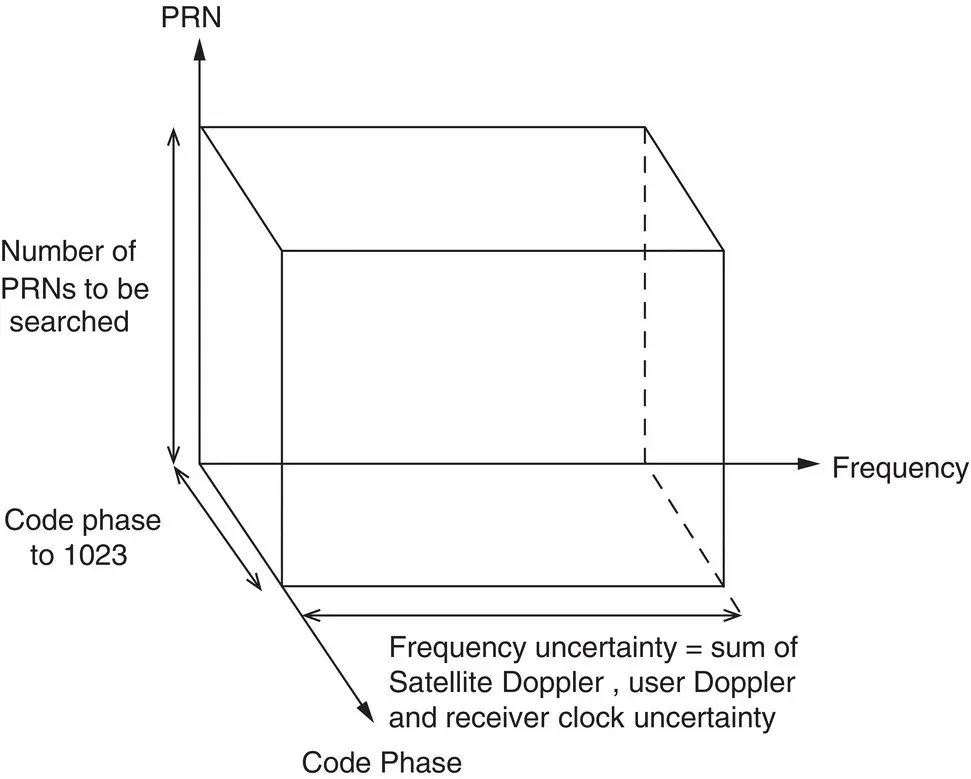
Figure 39.12 GPS search space.
The MBS search space also consists of the same three dimensions. However, the search space is effectively reduced to two dimensions when using the preamble for initial acquisition. The optional modulation pattern on the preamble (see Section 9.2 of [8]) can be used to facilitate a more robust slot alignment.
The preamble acquisition enables coarse frequency and code phase acquisition, which reduces pilot/data PRN search requirements. Once the initial preamble acquisition has been performed, the beacon‐specific PRNs need to be searched. The search space in code phase and frequency is reduced to the intersection of the gray boxes in Figure 39.13(a) and leads to a search space as shown in Figure 39.13(b) for the beacon PRN search. Once a beacon is detected, the search space for other beacons can be reduced, since their relative ranges in a terrestrial system will always be below the code duration of 1 ms.
Читать дальшеИнтервал:
Закладка:
Похожие книги на «Position, Navigation, and Timing Technologies in the 21st Century»
Представляем Вашему вниманию похожие книги на «Position, Navigation, and Timing Technologies in the 21st Century» списком для выбора. Мы отобрали схожую по названию и смыслу литературу в надежде предоставить читателям больше вариантов отыскать новые, интересные, ещё непрочитанные произведения.


Обсуждение, отзывы о книге «Position, Navigation, and Timing Technologies in the 21st Century» и просто собственные мнения читателей. Оставьте ваши комментарии, напишите, что Вы думаете о произведении, его смысле или главных героях. Укажите что конкретно понравилось, а что нет, и почему Вы так считаете.