Position, Navigation, and Timing Technologies in the 21st Century
Здесь есть возможность читать онлайн «Position, Navigation, and Timing Technologies in the 21st Century» — ознакомительный отрывок электронной книги совершенно бесплатно, а после прочтения отрывка купить полную версию. В некоторых случаях можно слушать аудио, скачать через торрент в формате fb2 и присутствует краткое содержание. Жанр: unrecognised, на английском языке. Описание произведения, (предисловие) а так же отзывы посетителей доступны на портале библиотеки ЛибКат.
- Название:Position, Navigation, and Timing Technologies in the 21st Century
- Автор:
- Жанр:
- Год:неизвестен
- ISBN:нет данных
- Рейтинг книги:5 / 5. Голосов: 1
-
Избранное:Добавить в избранное
- Отзывы:
-
Ваша оценка:
Position, Navigation, and Timing Technologies in the 21st Century: краткое содержание, описание и аннотация
Предлагаем к чтению аннотацию, описание, краткое содержание или предисловие (зависит от того, что написал сам автор книги «Position, Navigation, and Timing Technologies in the 21st Century»). Если вы не нашли необходимую информацию о книге — напишите в комментариях, мы постараемся отыскать её.
Volume 1 of
contains three parts and focuses on the satellite navigation systems, technologies, and engineering and scientific applications. It starts with a historical perspective of GPS development and other related PNT development. Current global and regional navigation satellite systems (GNSS and RNSS), their inter-operability, signal quality monitoring, satellite orbit and time synchronization, and ground- and satellite-based augmentation systems are examined. Recent progresses in satellite navigation receiver technologies and challenges for operations in multipath-rich urban environment, in handling spoofing and interference, and in ensuring PNT integrity are addressed. A section on satellite navigation for engineering and scientific applications finishes off the volume.
Volume 2 of
consists of three parts and addresses PNT using alternative signals and sensors and integrated PNT technologies for consumer and commercial applications. It looks at PNT using various radio signals-of-opportunity, atomic clock, optical, laser, magnetic field, celestial, MEMS and inertial sensors, as well as the concept of navigation from Low-Earth Orbiting (LEO) satellites. GNSS-INS integration, neuroscience of navigation, and animal navigation are also covered. The volume finishes off with a collection of work on contemporary PNT applications such as survey and mobile mapping, precision agriculture, wearable systems, automated driving, train control, commercial unmanned aircraft systems, aviation, and navigation in the unique Arctic environment.
In addition, this text:
Serves as a complete reference and handbook for professionals and students interested in the broad range of PNT subjects Includes chapters that focus on the latest developments in GNSS and other navigation sensors, techniques, and applications Illustrates interconnecting relationships between various types of technologies in order to assure more protected, tough, and accurate PNT
will appeal to all industry professionals, researchers, and academics involved with the science, engineering, and applications of position, navigation, and timing technologies.pnt21book.com
Position, Navigation, and Timing Technologies in the 21st Century — читать онлайн ознакомительный отрывок
Ниже представлен текст книги, разбитый по страницам. Система сохранения места последней прочитанной страницы, позволяет с удобством читать онлайн бесплатно книгу «Position, Navigation, and Timing Technologies in the 21st Century», без необходимости каждый раз заново искать на чём Вы остановились. Поставьте закладку, и сможете в любой момент перейти на страницу, на которой закончили чтение.
Интервал:
Закладка:
The comparison of the correlation function using the full GPS C/A spectrum of 20 MHz with PRN 7 and the MBS 2 MHz signal spectrum with one of the representative PRNs is shown in Figure 39.6. The figure shows clean autocorrelation side lobes for MBS codes relative to GPS code to facilitate multipath mitigation. Observe the slight widening of the correlation function for MBS relative to the correlation function for GPS at the peak in Figure 39.7due to the spectrally contained nature of the MBS signal. Figure 39.8shows the close‐in autocorrelation sidelobes. The close‐in MBS sidelobes due to the transmit filter have amplitude < 0.03 (i.e. at least 30 dB below the main peak).
The beacon transmissions are illustrated in Figure 39.9. Each transmission period is 1 second long and is partitioned into 10 slots of 100 ms each. The transmission periods are separated by ∆ Tseconds, where ∆ Tis greater than or equal to 1. Each transmitter is assigned at least one of 10 slots.
The beacon transmission within a slot is partitioned into a preamble section, a pilot section, and, optionally, a data section. All the three sections use spread‐spectrum signals with BPSK‐spread PRN codes that have a common spreading rate. The sections which are data modulated use BPSK modulation. The preamble section is transmitted by all beacons with a system‐wide common PRN sequence to enable quick synchronization. The pilot and data sections use the PRN spreading sequence allocated for that beacon. The pilot sections are either unmodulated or have known modulation. The pilot sections are meant to be used for ranging and allow the receiver to use coherent integration. The data sections contain the required information bits to facilitate MBS trilateration in a stand‐alone manner without the need for external data. The data may be encrypted to protect against spoofing of the MBS signal and to control receiver access. In order to facilitate TDMA operation, there is a guard period within each beacon transmission slot when the beacon is silent (i.e. does not transmit).
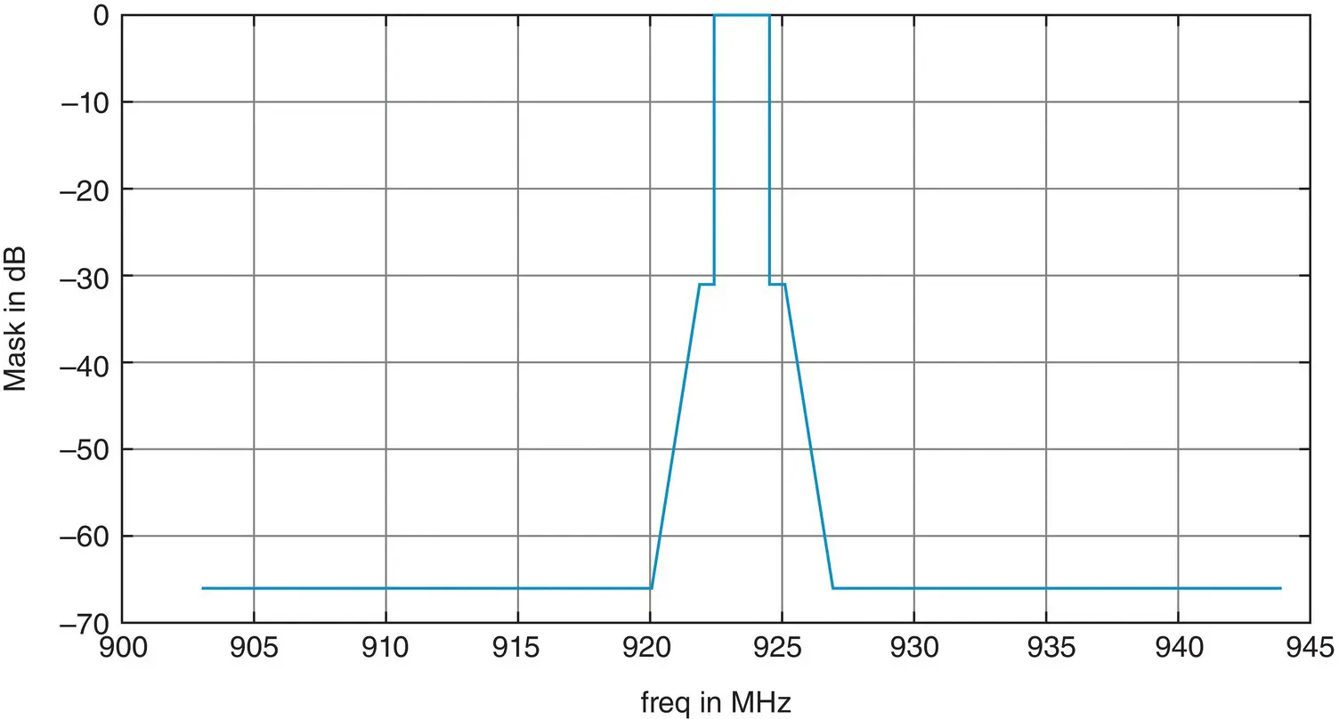
Figure 39.2 Spectral mask for the 2 MHz signal (GLONASS Interface Control Document [2]).
Source: Reproduced with permissions of Russian institute of Space Device Engineering.
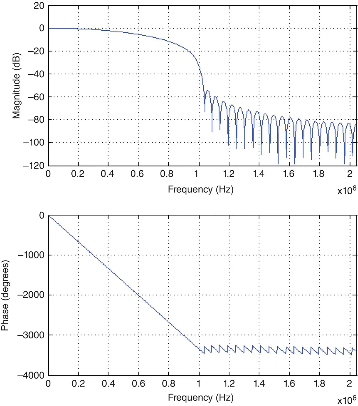
Figure 39.3 Amplitude and phase response of the MBS transmit filter as a function of frequency.
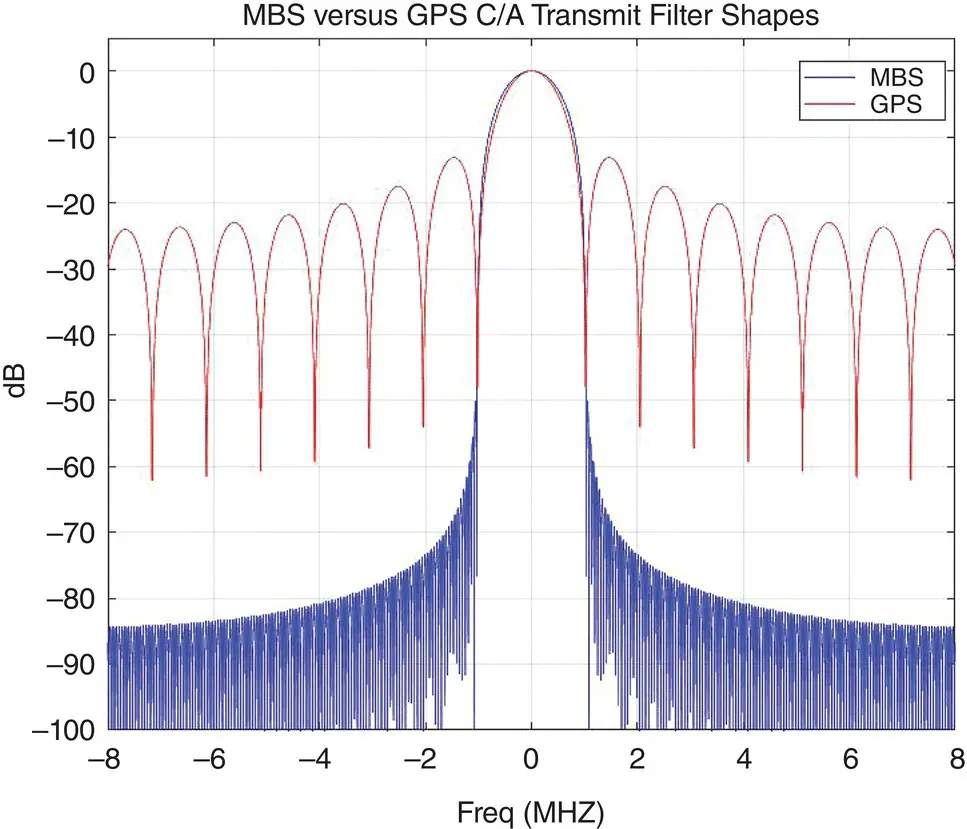
Figure 39.4 Frequency spectrum of MBS 2 MHz signal in comparison with GPS C/A code spectrum.
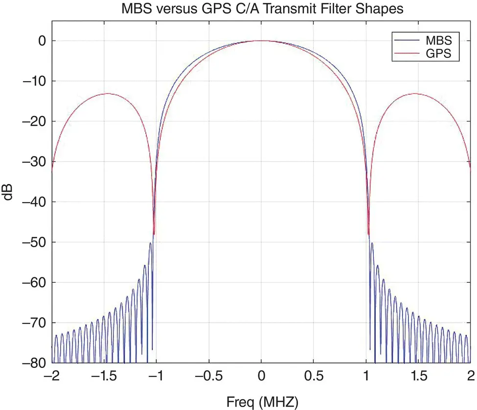
Figure 39.5 Zoomed‐in frequency spectrum of MBS 2 MHz signal in comparison with the GPS C/A code signal spectrum.
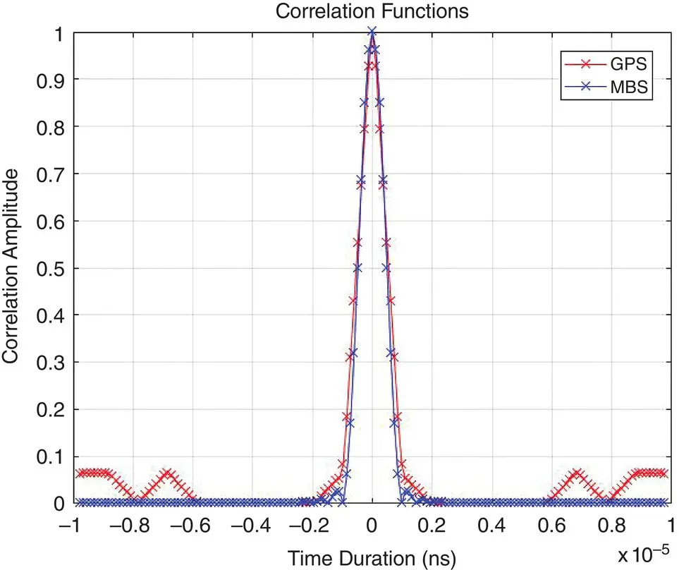
Figure 39.6 Correlation function of MBS compared with example of GPS code PRN 7.
A list of possible PN spreading codes used by the MBS is shown in the Appendix of [8].
As discussed above, each beacon transmits a preamble for a certain duration within its slot using a common spreading sequence across the network. The usage of a common spreading sequence allows the receiver to exclusively search for the preamble PRN to acquire the signal. The preamble enables the receiver to obtain frequency and slot synchronization using a relatively small amount of search resources since a single PRN search is only required to cover the frequency search dimension corresponding predominantly to receiver clock ppm uncertainty. Section 39.1.4.2discusses some more details of how the preamble is used to aid the acquisition process.

Figure 39.7 Correlation function of MBS and GPS at the peak.

Figure 39.8 Correlation function showing close‐in side lobes.
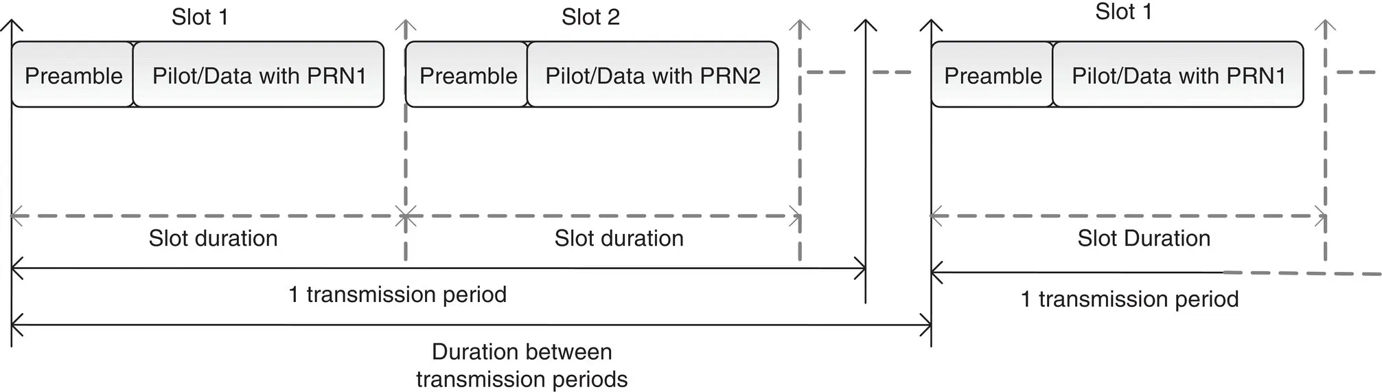
Figure 39.9 Beacon slot structure – preamble, pilot, and data sections.
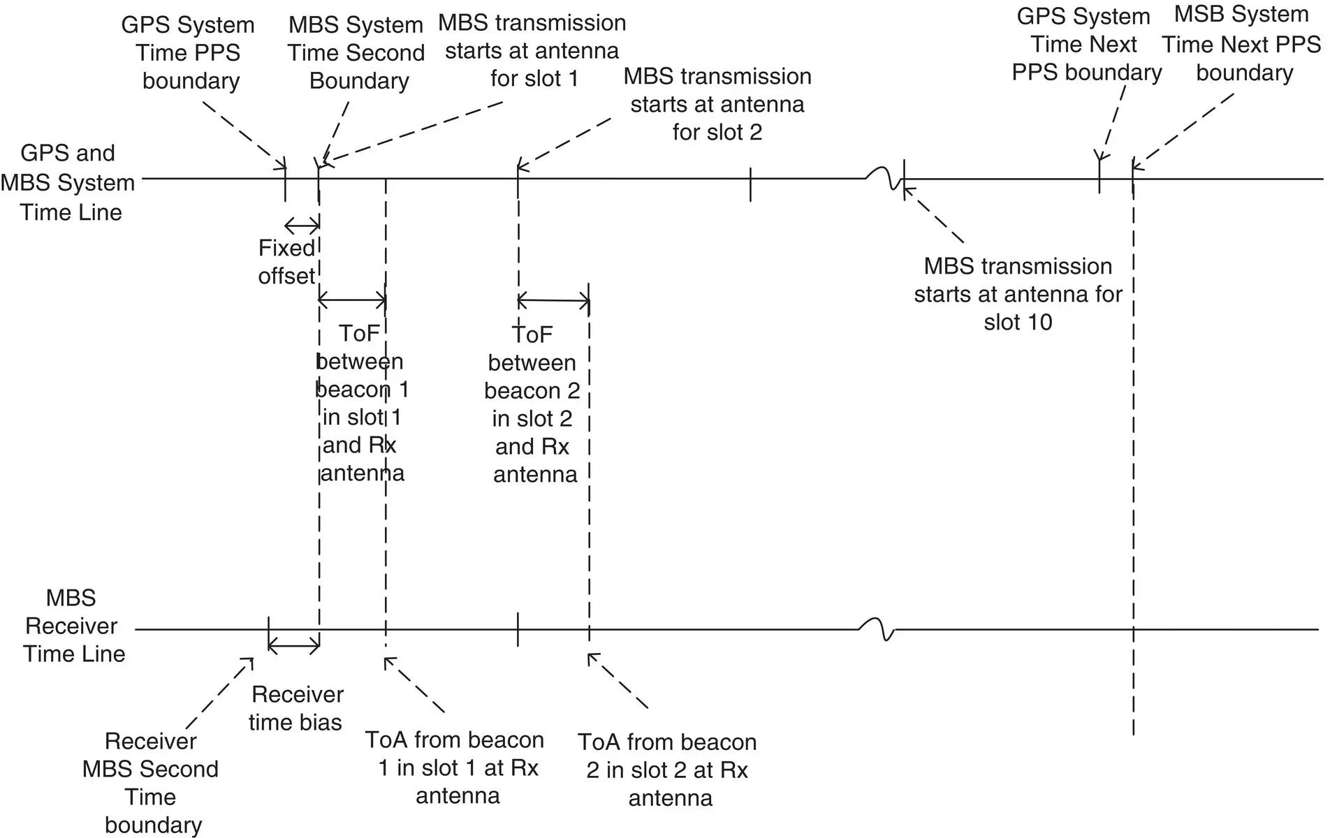
Figure 39.10 Relationship between GPS and MBS system timing.
The MBS system time is synchronized with GPS system time at an absolute level. Figure 39.10shows the MBS system time relationship with GPS system time, the relationship between MBS system time and MBS beacon transmissions, as well as the time of arrival (TOA) at the MBS receiver of the MBS beacon signals. As shown in Figure 39.10, MBS time equals GPS time + Fixed Offset. Note that all beacons are synchronized to transmit as per MBS system time. MBS system time is synchronized to the phase center of the transmit antenna. In the MBS signal transmission from the beacon, the peak of the first chip of the first preamble PRN sequence within a slot is aligned to MBS system time. The MBS transmission for beacons in the N‐th slot starts at an offset of ( N × 100) ms from the MBS system time second boundaries. Note that any fixed offset between MBS and GPS system time is transmitted through the data packets.
Figure 39.11shows a block diagram describing signal generation in an MBS transmitter. Note the similarity of the MBS signal generation section to the GPS C/A code transmit section [1]. The logic shown in Figure 39.11controls the selection of the PRN sequence (system‐wide preamble versus beacon‐specific pilot/data spreading sequence) for different parts of the slot as well as the optional beacon‐specific frequency offset for the pilot/data sections. The data packet content can consist of trilateration information, atmospheric information, timing information, and/or system control messages. The data content may also be encrypted to prevent unauthorized usage of the data stream. A forward error correction/detection scheme is added on the data frames to protect against channel errors. Once the spreading is done, pulse shaping is applied to generate the signal, which is then up‐converted to the MBS frequency and amplified before transmission over the air.
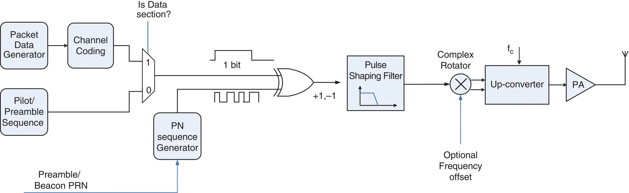
Figure 39.11 Transmitter block diagram.
39.1.3 Comparison of MBS Signal with GNSS Signals
Table 39.1shows a comparison between the GPS L1 C/A code signal and the MBS 2 MHz signal. The MBS system is a broadcast system similar to the GPS, the only difference being that the MBS system is terrestrially broadcast. The MBS is a spread‐spectrum system which has pretty much all its key characteristics identical to GPS C/A except that the spreading codes selected may be optimized for multipath. With regard to multiple access, the MBS system uses a combination of CDMA/TDMA/Frequency Offset Multiple Access, whereas the GPS system uses CDMA. The MBS system provides a cross‐correlation rejection of >40 dB as against the worst‐case CDMA code rejection of 23 dB in GPS systems. The MBS system’s beacon transmissions are synchronized to one another, just as for GPS satellite transmissions. The MBS data bit duration and coding in MBS are similar to the Wide Area Augmentation System (WAAS) or European Geostationary Navigation Overlay Service (EGNOS) systems. The MBS data content is, in general, analogous to the GPS data content with the MBS beacon coordinates corresponding to the GPS ephemeris/almanac and the MBS timing correction corresponding to the GPS satellite clock correction. Note also that MBS data may be encrypted using a conditional access scheme to control receiver access to the data stream. Location estimation using the MBS system is similar to the GPS system in that trilateration can be done using pseudorange measurements. The key difference is that the MBS trilateration process may estimate altitude independently using the receiver barometric pressure reading. The MBS receiver can operate in both stand‐alone and assisted modes, just as a GPS receiver. Also, the position may be computed at the receiver or at the server.
Читать дальшеИнтервал:
Закладка:
Похожие книги на «Position, Navigation, and Timing Technologies in the 21st Century»
Представляем Вашему вниманию похожие книги на «Position, Navigation, and Timing Technologies in the 21st Century» списком для выбора. Мы отобрали схожую по названию и смыслу литературу в надежде предоставить читателям больше вариантов отыскать новые, интересные, ещё непрочитанные произведения.


Обсуждение, отзывы о книге «Position, Navigation, and Timing Technologies in the 21st Century» и просто собственные мнения читателей. Оставьте ваши комментарии, напишите, что Вы думаете о произведении, его смысле или главных героях. Укажите что конкретно понравилось, а что нет, и почему Вы так считаете.