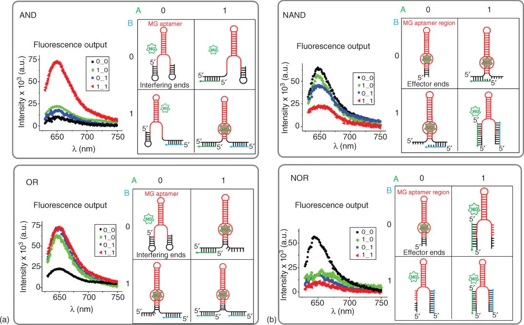
Figure 5.4Logic gates design principle using MG‐binding RNA aptamer. (a) Representative AND and OR gates showing fluorescence response and 2D RNA structures with no inputs, presence of one or both inputs. (b) Examples of NAND and NOR gates with fluorescence readouts and 2D structures of the RNA construct in response to presence of either input and both inputs.
Source: (Panel b) Adapted from Goldsworthy et al. [46].
AND Boolean logic has been successfully applied by using split RNA aptamer systems [89–93]. The design does not utilize DNA as input to trigger conformational changes of the aptamer structure. Instead, the RNA aptamer itself is bisected into a two‐component system. This allows the split aptamer to perform the AND logic function because two halves are required to bind the dye.
The NAND and NOR gates were designed slightly differently. The extensions at the 5′‐ and 3′‐ends of the core MG‐binding aptamer region were shorter (18 nt at the 5′‐end and 17 nt at the 3′‐end). These are non‐interfering ends; thus they do not cause disruption of the MG‐binding pocket. Therefore, in the absence of both inputs, 0‐0, the output is 1 ( Figure 5.4b). In NAND logic, the non‐interfering ends must be able to bind inputs A or B without changing the structure of the MG‐binding pocket. However, when both A and B are presented, the conformation of the aptamer needs to be sufficiently distorted to achieve OFF state. In NOR logic, the presence of either inputs significantly disrupts the conformation of the RNA molecule, rendering MG binding impossible. Hence, the output was “1” only in the absence of both potential DNA inputs.
Programs such as NUPAC and mfold are often used to design DNA–RNA aptamers with MG‐binding potential. Unfortunately, these programs cannot analyze stability of hybrid RNA–DNA interactions. Since the overall design relies primarily on the strand displacement reaction between RNA–RNA and RNA–DNA interactions, the folding predictions might be inaccurate. To overcome this, various concentrations of RNA gates and DNA inputs should be explored to gain better ON and OFF separation threshold.
5.3.2 Implementation of MG‐Binding RNA Aptamer and Broccoli RNA Aptamer to Design Half‐Adder Circuit
Simplest level circuits like half‐adders and full‐adders include combinations of logic gate operations. The half‐adder circuit can be constructed from combinations of logic functions AND and XOR with two inputs and two outputs: SUM (XOR gate) and CARRY (AND gate). The half‐adder is used for adding together the two least significant digits in a binary sum ( Figure 5.5). The four possible combinations of binary digits A and B are shown in Figurenbsp; 5.5(a) where the sum of the two digits is given for each of these combinations. For case A = 1 and B = 1, the sum is 10, where the 1 generated is the CARRY to the next stage of the addition.
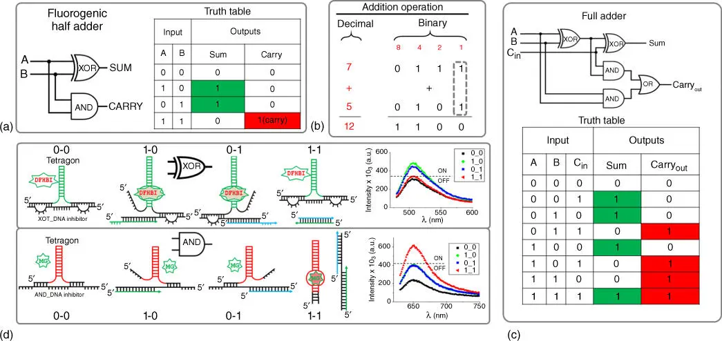
Figure 5.5Examples of combinatorial logic gates using half‐adder and full‐adder. (a) Half‐adder circuit diagram containing XOR and AND logic gates and its truth table. (b) Example of addition operation by the half‐adder that adds the two least significant bits highlighted in puncture/dashed line. (c) Circuit schematic and truth table for full‐adder. (d) Secondary structures demonstrating design principles for the Broccoli aptamer (XOR gate) and MG RNA aptamer (AND gate) and their fluorescence outputs in response to DNA inputs.
Source: (Panel c) Adapted from Goldsworthy et al. [46]; (Panel d) From Goldsworthy et al. [46]. Licensed under CC by 4.0.
An RNA tetragonal structure with infusion of two different light‐up RNA aptamers acting as AND (MG‐binding aptamer) and XOR (Broccoli aptamer) gates was fused into a tetragonal particle to fabricate the half‐adder circuit. These gates utilize the same DNA inputs but produce two distinctly different fluorescence emissions as output signals, SUM ( λ em= 510 nm) and CARRY ( λ em= 650 nm). Both the MG RNA aptamer and Broccoli RNA aptamers were incorporated on alternating vertices of the tetragon. To satisfy the XOR and AND truth values (in absence of inputs 0‐0 the output must be OFF), additional DNA inhibitor (XOR_DNA and AND_DNA inhibitors) strands were introduced to interfere the corresponding ON states of both aptamers ( Figure 5.5c). The fluorescence readout corresponding to XOR and AND operations was achieved by relying on the displacement principle between inhibitor DNA strands, DNA inputs, and RNA aptamers. Specific design approaches including RNA and DNA sequences chosen for combinatorial implementation of the AND and the XOR gates to satisfy the requirements for a half‐adder have been published [46]. The next step is construction of a full‐adder based on RNA light‐up aptamer, which has yet to be achieved. The full‐adder circuits extend the concept of the half‐adder by providing an additional carry‐in (Cin) input as demonstrated in the diagram in Figure 5.5c. This design has three inputs (A, B, and Cin) and two outputs (Sum and Carry‐out).
The integration of advances in nucleic acid nanotechnology and in nucleic acid aptamer technologies makes it possible to build novel nanoparticles playing intermediate roles between electronic computers and biological systems. Programming with biological molecules, especially with nucleic acids (NA), is now becoming very attractive due to their potential of functions ranging from simple fluorescence emission to sophisticated gene regulation in vivo . The structural behavior encompassed within their sequences can be predicted and manipulated using 2D folding algorithms. The resulting nucleic acid biopolymers can then be used as logic‐gated nano‐agents for specific biomedical applications. Fluorogenic RNA aptamers can be designed to function as a simple circuit within individual binary logic gates. This demonstrates the great potential of nucleic acid nanotechnology and holds promise to develop cutting‐edge technologies, especially if synergistically combined with other computing and nanorobotic systems.
This work was supported by the National Institute of Biomedical Imaging and Bioengineering of the National Institutes of Health under Award Number R03EB027910. The content is solely the responsibility of the authors and does not necessarily represent the official views of the National Institutes of Health.
1 1 Cinteza, L.O. (2010). Quantum dots in biomedical applications: advances and challenges. J. Nanophotonics 4 (Art. No.: 042503) https://doi.org/10.1117/1.3500388.
2 2 Wagner, A.M., Knipe, J.M., Orive, G., and Peppas, N.A. (2019). Quantum dots in biomedical applications. Acta Biomater. 94: 44–63. https://doi.org/10.1016/j.actbio.2019.05.022.
3 3 Jeevanandam, J., Barhoum, A., Chan, Y.S. et al. (2018). Review on nanoparticles and nanostructured materials: history, sources, toxicity and regulations. Beilstein J. Nanotechnol. 9: 1050–1074. https://doi.org/10.3762/bjnano.9.98.
4 4 Iriarte‐Mesa, C., Lopez, Y.C., Matos‐Peralta, Y. et al. (2020). Gold, silver and iron oxide nanoparticles: synthesis and bionanoconjugation strategies aimed at electrochemical applications. Top. Curr. Chem. (Cham) 378: 12. https://doi.org/10.1007/s41061-019-0275-y.
5 5 Mirahadi, M., Ghanbarzadeh, S., Ghorbani, M. et al. (2018). A review on the role of lipid‐based nanoparticles in medical diagnosis and imaging. Ther. Deliv. 9: 557–569. https://doi.org/10.4155/tde-2018-0020.
Читать дальше
