Stephen M. Rowland - Structural Analysis and Synthesis
Здесь есть возможность читать онлайн «Stephen M. Rowland - Structural Analysis and Synthesis» — ознакомительный отрывок электронной книги совершенно бесплатно, а после прочтения отрывка купить полную версию. В некоторых случаях можно слушать аудио, скачать через торрент в формате fb2 и присутствует краткое содержание. Жанр: unrecognised, на английском языке. Описание произведения, (предисловие) а так же отзывы посетителей доступны на портале библиотеки ЛибКат.
- Название:Structural Analysis and Synthesis
- Автор:
- Жанр:
- Год:неизвестен
- ISBN:нет данных
- Рейтинг книги:5 / 5. Голосов: 1
-
Избранное:Добавить в избранное
- Отзывы:
-
Ваша оценка:
Structural Analysis and Synthesis: краткое содержание, описание и аннотация
Предлагаем к чтению аннотацию, описание, краткое содержание или предисловие (зависит от того, что написал сам автор книги «Structural Analysis and Synthesis»). Если вы не нашли необходимую информацию о книге — напишите в комментариях, мы постараемся отыскать её.
As is explicit in the title, this book is concerned with both the analysis and synthesis of structural features. In this 4th edition, the focus of this popular manual has been broadened to include a range of new content and features, including:
Video content which demonstrates visually how to perform some of the more challenging structural geology techniques An acknowledgement of the increasing importance of environmental applications of structural geology – vital to students who may go on to pursue careers in the environmental sphere An increased emphasis on quantitative techniques, complete with descriptions of computer program applications Contingent with this quantitative emphasis, the book also outlines the limitations of such techniques, helping students to appropriately apply the techniques and evaluate their trustworthiness
is a renowned and widely recognized aid to students in grasping and mastering the techniques required in structural geology, and will find a home wherever the principles and practices of structural geology are taught.
Structural Analysis and Synthesis — читать онлайн ознакомительный отрывок
Ниже представлен текст книги, разбитый по страницам. Система сохранения места последней прочитанной страницы, позволяет с удобством читать онлайн бесплатно книгу «Structural Analysis and Synthesis», без необходимости каждый раз заново искать на чём Вы остановились. Поставьте закладку, и сможете в любой момент перейти на страницу, на которой закончили чтение.
Интервал:
Закладка:
Figure 1.6 Topographic map showing linear ridges and the line to measure structural grain of a ridge.
Karst topography is common in temperate areas underlain by limestone. One of the main features of karst is the formation of sinkholes. In many cases, the location of sinkholes is controlled by joints, joint systems/fracture trends, and brittle faults. In particular, sinkholes are common at the intersection of joints or faults. Aligned sinkholes can define zones of joints (fracture zones). By measuring the bearing of aligned sinkholes, the alignment of such brittle features may be determined.
In some cases, an indication of dip can also be determined from the topography. If the more resistant units that make up the ridges are shallowly dipping, there will typically be a dip slope and a strike or scarp slope. The steeper side of the ridge results from erosion of the unit face and is the strike slope. The shallower side of the ridge generally follows the dip of the bed. The dip direction is in the direction of the shallow side and the strike approximately follows the structural grain of a ridged area.
Problem 1.6
Using the map in Figure P1.3, determine the structural grain of the areas indicated. Also, determine the dip direction where possible.
| Location | Structural grain | Dip direction? |
| a | ||
| b | ||
| c | ||
| d | ||
| e |
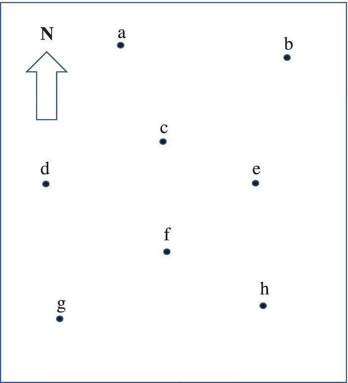
Figure P1.1 Base map on which to plot structural symbols in Problem 1.4.
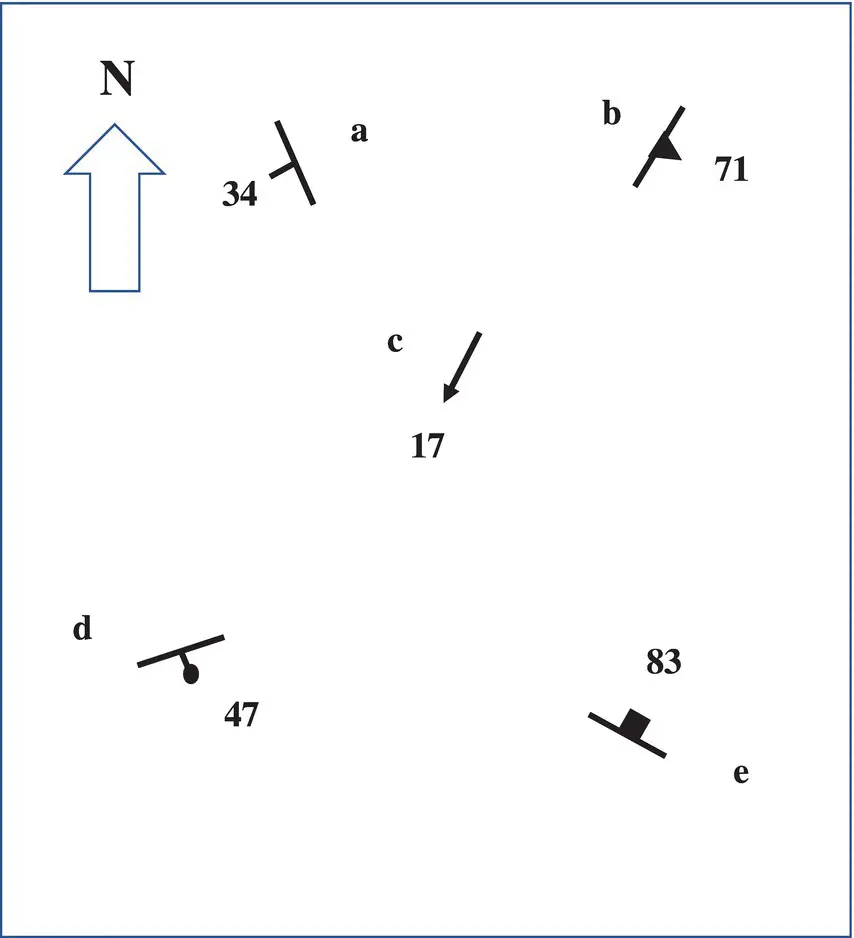
Figure P1.2 Map with structural symbols to be read back in Problem 1.5.
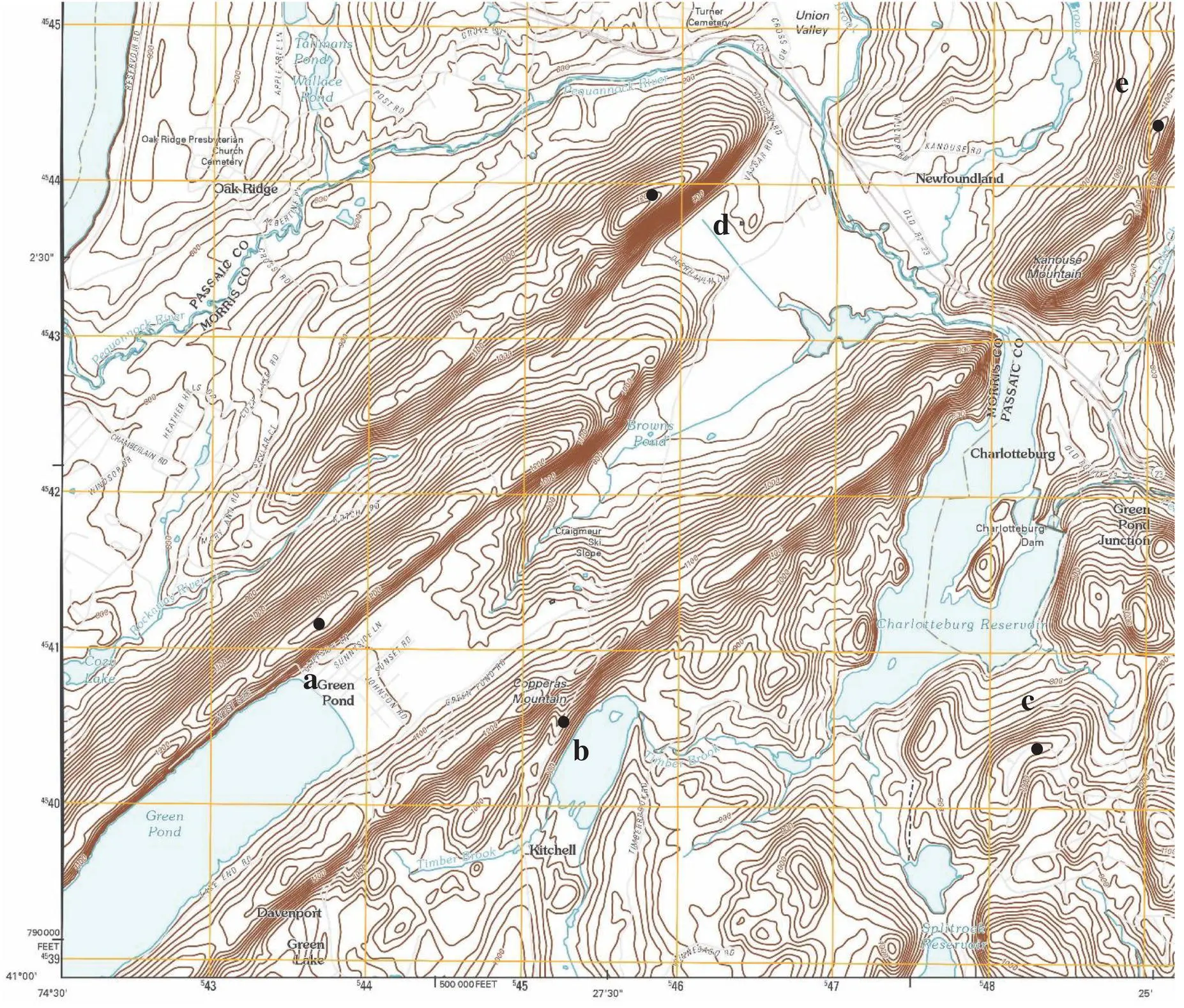
Figure P1.3 Topographic map showing linear ridges with uneven slopes to measure structural grain and possible dip direction in Problem 1.6.
2 Outcrop Patterns and Structure Contours
Objectives
Determine the general attitudes of planes from outcrop patterns.
Draw structure‐contour maps.
Solve three‐point problems.
Determine outcrop patterns of planar layers from attitudes at isolated outcrops.
Determine the nature of contacts from outcrop patterns and attitudes.
Determine stratigraphic thickness from outcrop pattern.
One of the primary roles of a geologist is to quantitatively determine subsurface structural relations from surface and/or well data. Your skills to address this will be developed starting with planar features and progressing to more complex structures. Planar structural elements such as contacts between monoclinal beds, dikes, and faults form irregular outcrop patterns on the uneven earth's surface. In situations where strike and dip symbols are not provided (such as on regional, small‐scale maps), outcrop patterns can serve as clues to the orientations of the planes. These relations should also be used for constructing maps from field data. The following are seven generalized cases showing the relationships between topography and the outcrop patterns of planes as seen on a map. As you examine Figures 2.1– 2.7, cover the block diagram (parts a) and try to visualize the orientation of the bed from its outcrop pattern in map view (parts b). Note the strike and dip symbols that indicate orientation.
1 Horizontal planes/contacts parallel topographic contour lines. They also “V” or point upstream but this is not unique ( Figure 2.1).
2 Vertical planes/contacts are not deflected at all by valleys or ridges ( Figure 2.2).
3 Moderate to steeply inclined planes “V”/point opposite to the direction of dip across horizontal or shallowly inclined ridges ( Figure 2.3).
4 Planes/contacts that dip upstream also “V” upstream ( Figure 2.4).
5 Planes/contacts that dip downstream at the same dip angle as the stream gradient appear parallel to the stream bed ( Figure 2.5). Figure 2.1 Horizontal layer in a stream valley. (a) Block diagram. (b) Map view. Figure 2.2 Vertical layer strikes perpendicular across a ridge and valley. (a) Block diagram. (b) Map view. Figure 2.3 Inclined layer strikes perpendicular across a horizontal ridge. (a) Block diagram. (b) Map view.
6 Planes/contacts that dip downstream at a gentler angle than the stream gradient “V”/point upstream ( Figure 2.6).
7 Planes/contacts that dip downstream at a steeper angle than the stream gradient (the usual case) “V”/point downstream ( Figure 2.7).
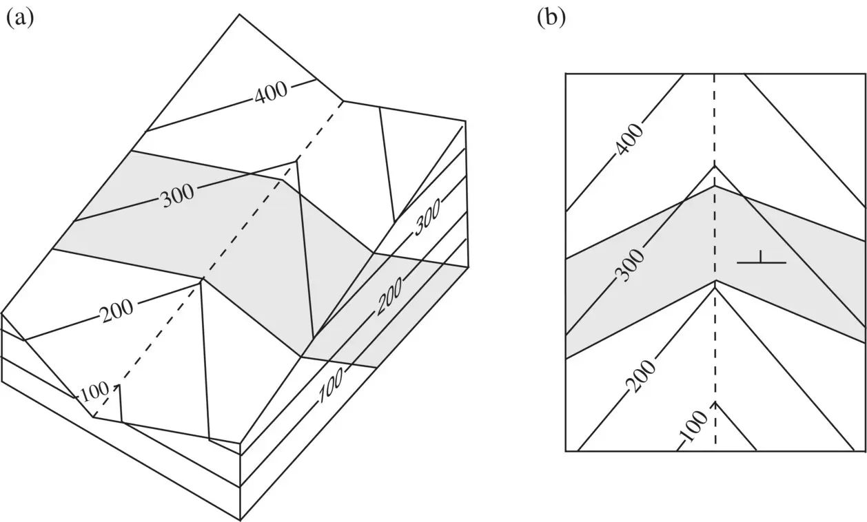
Figure 2.4 Inclined layer dipping upstream that flows 90° to strike. (a) Block diagram. (b) Map view.
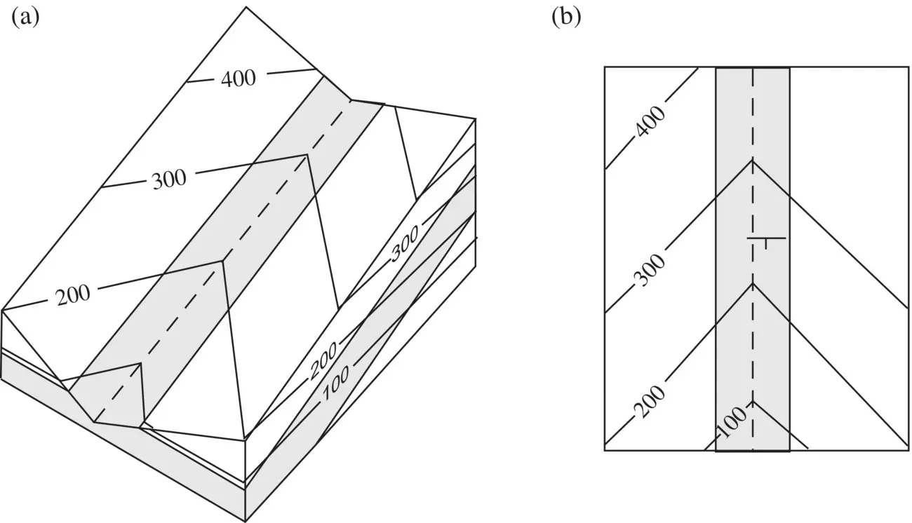
Figure 2.5 Layer dipping parallel to stream gradient (perpendicular strike). (a) Block diagram. (b) Map view.
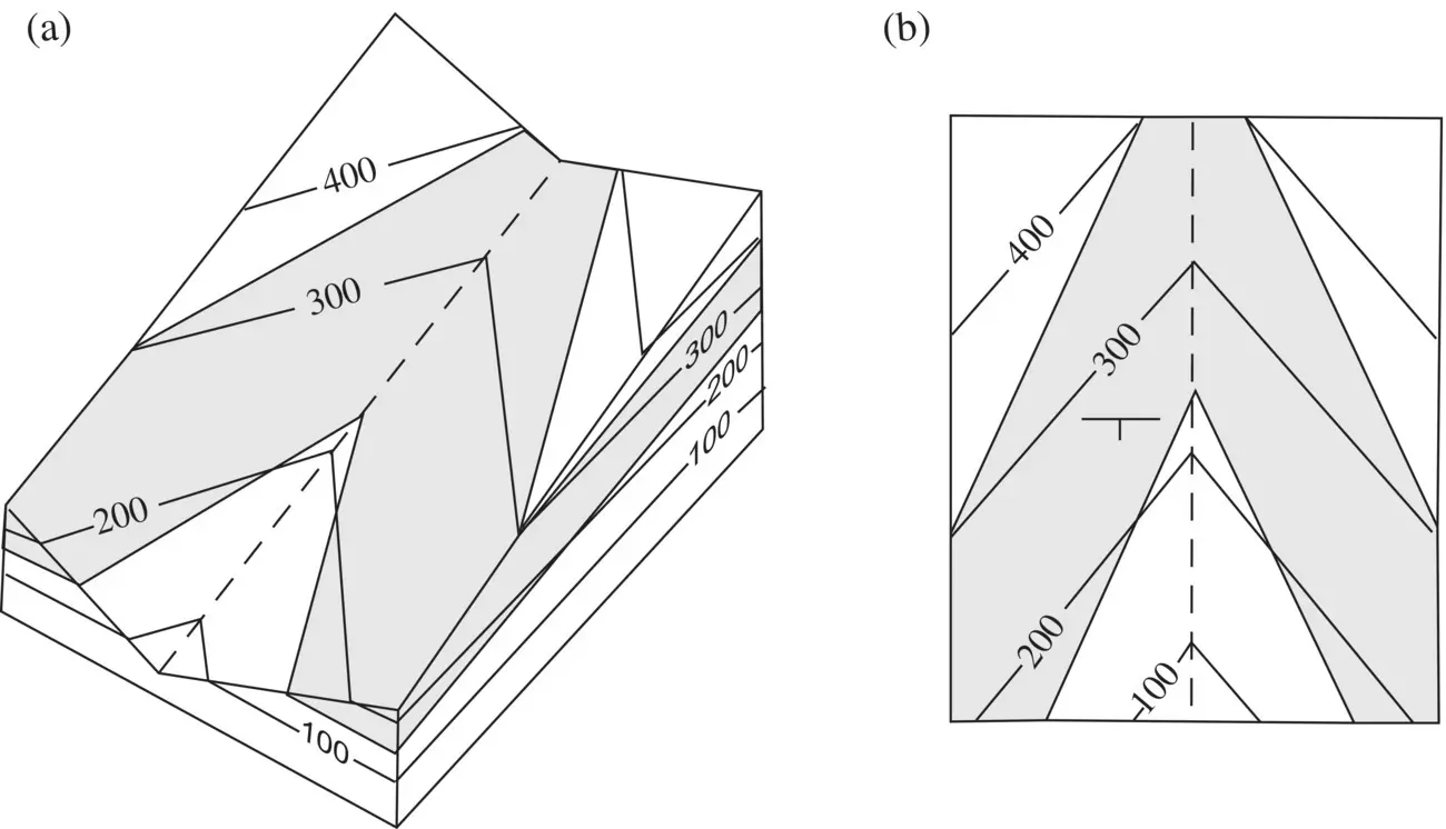
Figure 2.6 Layer dipping downstream more gently than the stream gradient with strike perpendicular to stream. (a) Block diagram. (b) Map view.
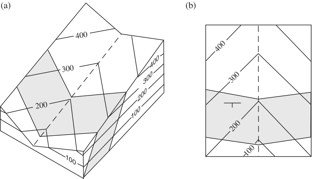
Figure 2.7 Layer dipping downstream more steeply than the stream gradient; stream perpendicular to strike. (a) Block diagram. (b) Map view.
Problem 2.1
On the geologic map in Figure P2.1, draw the correct strike and dip symbol in each circle to indicate the attitude of Formation B and each dike. To verify your attitude symbols, Figure P2.2can be cut out and folded to form a block model of this map. Table 1.1shows standard symbols for geologic maps.
Structure Contours
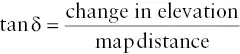
On a topographic map, contour lines connect points of equal elevation on the earth's surface. In contrast, structure contour is a line that connects points of equal elevation from sea level on a structural surface , such as the top of a bed or formation ( Figure 2.8). This means that the orientation of a structure contour is parallel to the strike of the bed or other structural element. Dip direction is perpendicular to the structure contour and directly downslope. Structure contours are read and analyzed the same way as topographic contours, in most cases. For example, calculating dip angles is done the same way as calculating slope angles from topographic contours. Both use the formula:
Structure‐contour maps are used for depiction and recognition of features in the subsurface. They are used extensively in petroleum exploration to identify structural traps and in hydrology to characterize the subsurface configurations of water tables and aquifers. Although there are more sophisticated methods to model the hydrogeology of an area, structure contouring of the water table is an invaluable skill for all geologists working on environmental delineation/remediation projects.
Читать дальшеИнтервал:
Закладка:
Похожие книги на «Structural Analysis and Synthesis»
Представляем Вашему вниманию похожие книги на «Structural Analysis and Synthesis» списком для выбора. Мы отобрали схожую по названию и смыслу литературу в надежде предоставить читателям больше вариантов отыскать новые, интересные, ещё непрочитанные произведения.


Обсуждение, отзывы о книге «Structural Analysis and Synthesis» и просто собственные мнения читателей. Оставьте ваши комментарии, напишите, что Вы думаете о произведении, его смысле или главных героях. Укажите что конкретно понравилось, а что нет, и почему Вы так считаете.