Stephen M. Rowland - Structural Analysis and Synthesis
Здесь есть возможность читать онлайн «Stephen M. Rowland - Structural Analysis and Synthesis» — ознакомительный отрывок электронной книги совершенно бесплатно, а после прочтения отрывка купить полную версию. В некоторых случаях можно слушать аудио, скачать через торрент в формате fb2 и присутствует краткое содержание. Жанр: unrecognised, на английском языке. Описание произведения, (предисловие) а так же отзывы посетителей доступны на портале библиотеки ЛибКат.
- Название:Structural Analysis and Synthesis
- Автор:
- Жанр:
- Год:неизвестен
- ISBN:нет данных
- Рейтинг книги:5 / 5. Голосов: 1
-
Избранное:Добавить в избранное
- Отзывы:
-
Ваша оценка:
Structural Analysis and Synthesis: краткое содержание, описание и аннотация
Предлагаем к чтению аннотацию, описание, краткое содержание или предисловие (зависит от того, что написал сам автор книги «Structural Analysis and Synthesis»). Если вы не нашли необходимую информацию о книге — напишите в комментариях, мы постараемся отыскать её.
As is explicit in the title, this book is concerned with both the analysis and synthesis of structural features. In this 4th edition, the focus of this popular manual has been broadened to include a range of new content and features, including:
Video content which demonstrates visually how to perform some of the more challenging structural geology techniques An acknowledgement of the increasing importance of environmental applications of structural geology – vital to students who may go on to pursue careers in the environmental sphere An increased emphasis on quantitative techniques, complete with descriptions of computer program applications Contingent with this quantitative emphasis, the book also outlines the limitations of such techniques, helping students to appropriately apply the techniques and evaluate their trustworthiness
is a renowned and widely recognized aid to students in grasping and mastering the techniques required in structural geology, and will find a home wherever the principles and practices of structural geology are taught.
Structural Analysis and Synthesis — читать онлайн ознакомительный отрывок
Ниже представлен текст книги, разбитый по страницам. Система сохранения места последней прочитанной страницы, позволяет с удобством читать онлайн бесплатно книгу «Structural Analysis and Synthesis», без необходимости каждый раз заново искать на чём Вы остановились. Поставьте закладку, и сможете в любой момент перейти на страницу, на которой закончили чтение.
Интервал:
Закладка:
Using the rules of Vs, the outcrop pattern in Figure 2.16a indicates that the beds dip toward the south. To determine the exact dip, draw a line that is perpendicular to the strike line from another point of known elevation on the contact. In Figure 2.16c, a line is drawn from the strike line to a point where the contact crosses the 1680‐ft contour. The length of this line ( h ) and the change in elevation ( v ) from the strike line to this point yield the dip δ with the following equation ( Figure 2.16d):
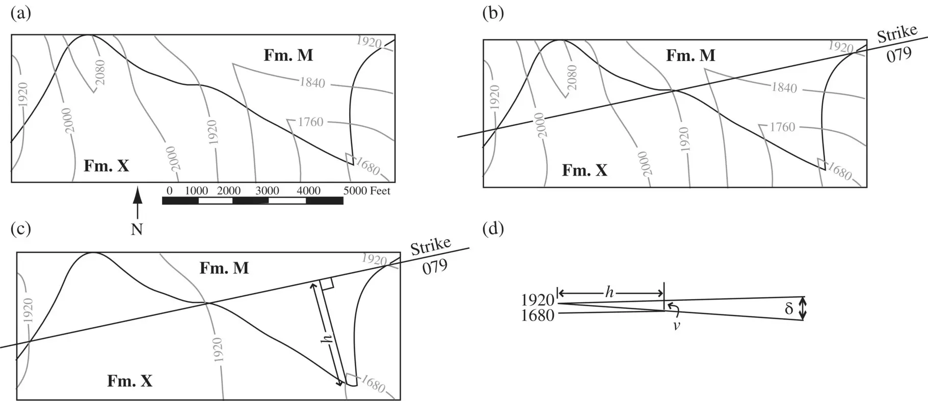
Figure 2.16 Technique for determining the orientation of a plane from its outcrop pattern. (a) Contact between Formation M and Formation X on a topographic map. (b) The line connecting points of equal elevation defines the strike. (c) A perpendicular is drawn to a point of contact at a different elevation. (d) Dip angle δ is found from tan δ = v / h .

The solution to this example is:
This method for determining attitudes from outcrop patterns can only be used if the beds are planar.
Figure 2.17shows the Neogene (Miocene and Pliocene) units of the Bree Creek area. Straight lines have been drawn connecting points of known elevation on the bottom contact of the unit Tr. The strike, measured directly on the map with a protractor, is 344° (N16W), and the dip is 11°NE as determined by:
Determining Stratigraphic Thickness in Flat Terrain
If the attitude of a rock unit is known, it is usually possible to determine its approximate stratigraphic thickness from a geologic map. If a unit is steeply dipping, and if its upper and lower contacts are exposed on flat or nearly flat terrain, then the thickness is determined from the trigonometric relationship.
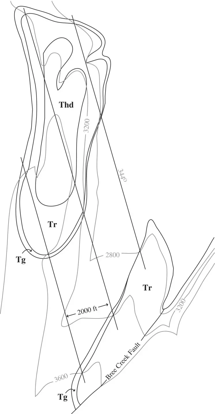
Figure 2.17 Neogene units in the Bree Creek area. Tg = Conglomerate; Thd = Sandstone; Tr = Tuff.

where t is stratigraphic thickness, h is horizontal thickness (map width), and δ is dip ( Figure 2.18).
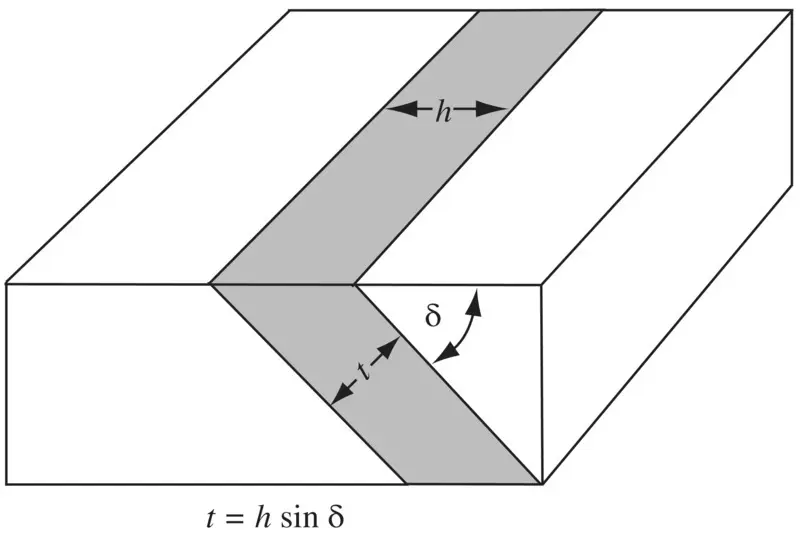
Figure 2.18 Trigonometric relationships used for determining stratigraphic thickness t in flat terrain from dip δ and map width h .
Determining Stratigraphic Thickness on Slopes
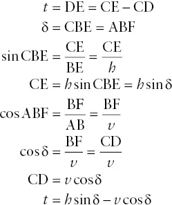
The thickness of layers exposed on slopes may be determined trigonometrically if, in addition to dip δ and map width h , the vertical distance v (i.e. difference in elevation) from the base to the top of the layer is known. Figure 2.19a shows a layer and the slope dipping in the same direction. Relevant angles are added in Figure 2.19b, from which the following derivation is made:
This relationship applies to situations where bedding dips more steeply than topography and both dip in the same direction (right‐side example in Figure 2.20). Similar trigonometric derivations can be used to show that in situations where bedding dips more gently than topography and both dip in the same direction (left‐side example in Figure 2.20), the equation is:
Where bedding and topography dip in opposite directions (middle example of Figure 2.20) the equation is:
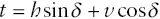
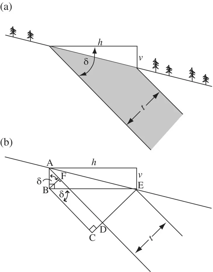
Figure 2.19 Determining stratigraphic thickness t on slopes. (a) Lengths h and v and dip angle δ are needed to derive t . (b) Geometry of derivation.
Determining Stratigraphic Thickness by Orthographic Projection
In some situations, the preceding trigonometric techniques for determining stratigraphic thickness cannot be used. In Bree Creek the 400‐ft contour interval does not allow the difference in elevation from the base to the top of a unit to be precisely determined. In such cases, orthographic projection can be used to determine stratigraphic thickness.
To determine the thickness of the Conglomerate (Tg) in the Bree Creek area, begin by finding two points of equal elevation at the same stratigraphic level. A line between such points defines the strike. In Figure 2.21a, a line is drawn through the top of Tg at 4800 ft., and another is drawn through the top of Tg at 4400 ft. The objective of this construction is to draw a vertical cross section perpendicular to strike.
Line AB is drawn perpendicular to the two strike lines ( Figure 2.21a). This represents the 4800‐ft elevation line in the orthographic projection. A second line, CD, is drawn, perpendicular to the two strike lines. Line CD represents the 4400‐ft elevation line. The distance between lines AB and CD is taken directly off the map. Next line AD is drawn, which represents the eastward‐dipping top of Tg in orthographic projection.
Repeating this procedure with the bottom contact of Tg results in points W, X, Y, and Z ( Figure 2.21b). Line WZ represents the base of Tg in orthographic projection, and the thickness can be measured directly off the diagram. The precision is primarily limited by the scale of the map. In this example, Tg can be measured to be about 100 ft thick.
Figure 2.20 Three combinations of sloping topography and dipping layers, with the appropriate formula for each.
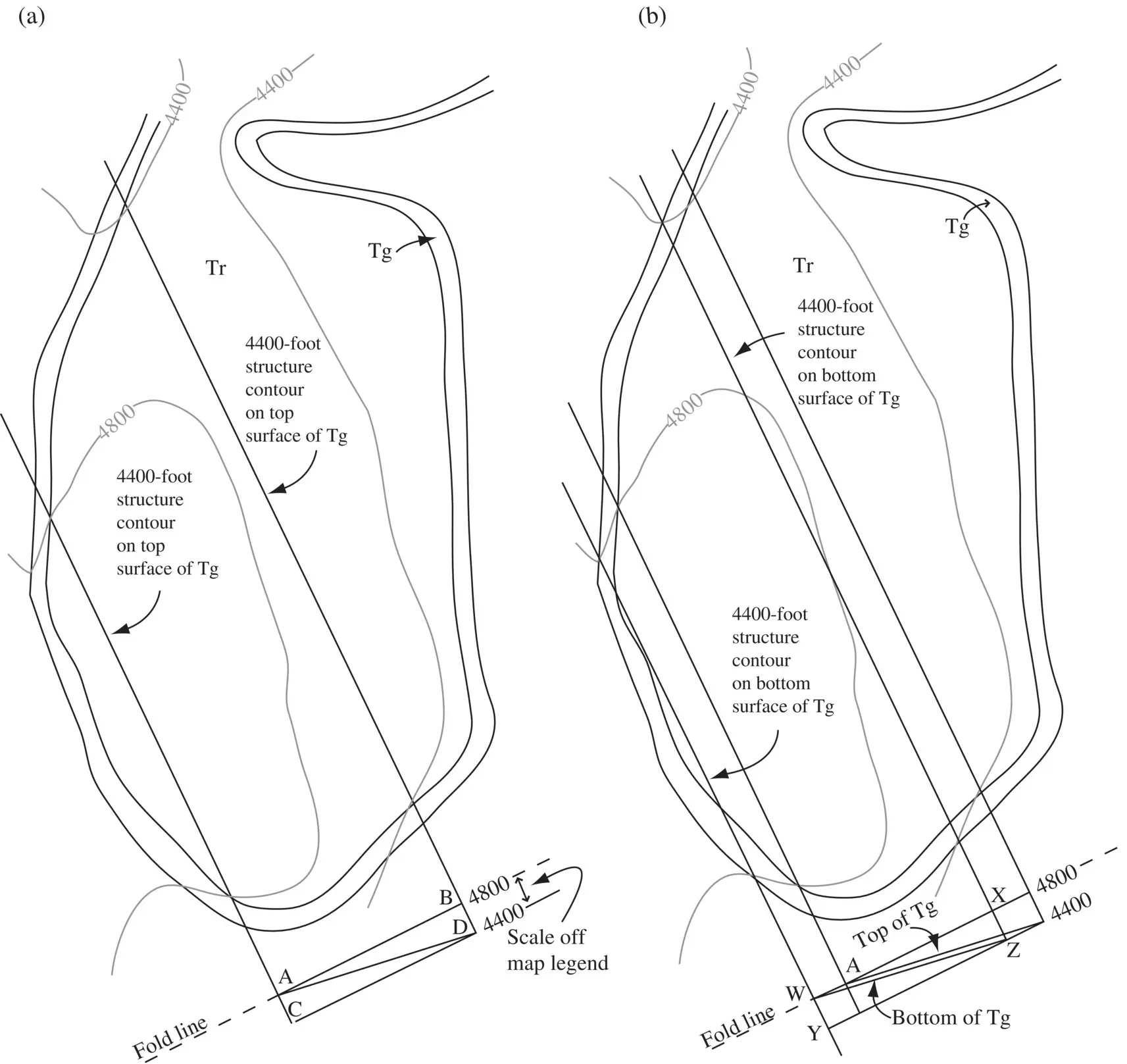
Figure 2.21 Technique for determining stratigraphic thickness by orthographic projection. (a) Plotting top surface. (b) Plotting bottom surface and deriving the thickness.
Figure P2.1 Map of an area showing contacts and topographic contours to be used with Problem 2.1.
Читать дальшеИнтервал:
Закладка:
Похожие книги на «Structural Analysis and Synthesis»
Представляем Вашему вниманию похожие книги на «Structural Analysis and Synthesis» списком для выбора. Мы отобрали схожую по названию и смыслу литературу в надежде предоставить читателям больше вариантов отыскать новые, интересные, ещё непрочитанные произведения.


Обсуждение, отзывы о книге «Structural Analysis and Synthesis» и просто собственные мнения читателей. Оставьте ваши комментарии, напишите, что Вы думаете о произведении, его смысле или главных героях. Укажите что конкретно понравилось, а что нет, и почему Вы так считаете.