4 Connect the points and draw the planar features using a ruler ( Figure 2.12).
Determining Outcrop Patterns with Structure Contours
If an important planar horizon is exposed in three places on a topographic map as in Figure 2.13a, its outcrop pattern can be determined on a topographic map. This is done by using the three‐point solution and locating the intersections of the structure contours with the topographic contours. This is accomplished using the following technique:
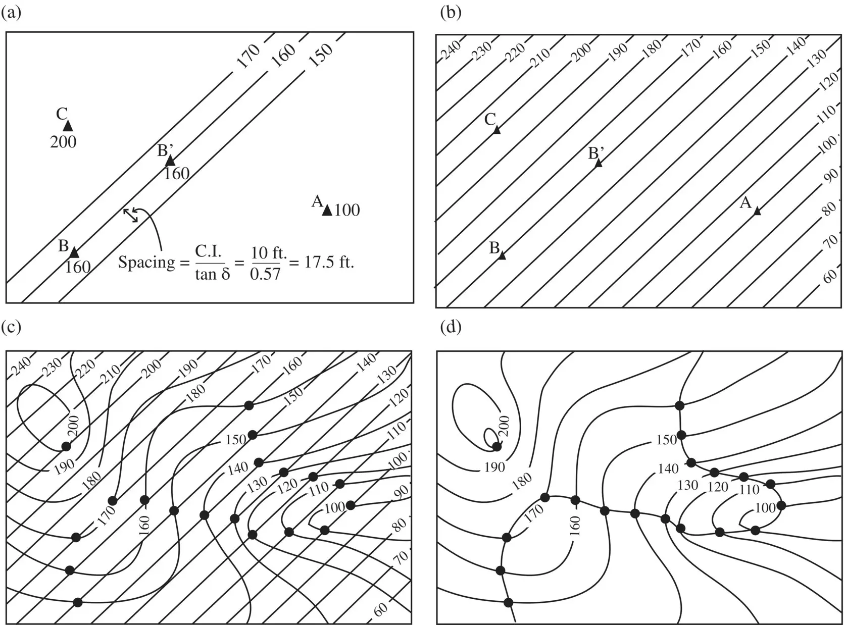
1 Draw structure contours parallel to the line B–B′ ( Figure 2.10d). In order to determine the outcrop pattern, these structure contours must have a contour interval equal to (or a multiple of) the contour interval on the topographic map. Because the surface is planar, the structure contours are a series of straight, equidistant, parallel lines. The spacing can be determined using the interpolation described or using: Figure 2.12 Technique for drawing a cross section. The top diagram is a map with surface and structure contours and the bottom is a geologic cross section. Transfer points to corresponding elevations on the topographic profile. Transfer two or more structure contours to another sheet of paper. Connect points to complete the cross section.In this example, the spacing (d) is 17.5 ft in map view ( Figure 2.13a). Point B is at an elevation of 160 ft, which is conveniently also the elevation of a topographic contour. Points on the bedding plane with known elevations (points A and C in this problem) serve as control points to make sure that the elevations of known outcrop points match their elevations on the structure‐contour map. Figure 2.13b shows the completed structure‐contour map.
2 On the superimposed structure‐contour map and topographic map ( Figure 2.13c), every point where a structure contour crosses a topographic contour of equal elevation is a surface outcrop. The outcrop map is made by marking each point where topographic and structure contours of the same elevation cross. Connect the points of intersection to display the outcrop pattern on the topographic map ( Figure 2.13d).
This same technique can be used to locate a second surface that is parallel to the first. If the contact shown in Figure 2.13d is the top of a bed, we can determine the outcrop pattern of the bottom of the bed as well. If a single outcrop point on the topographic map is known, then the outcrop pattern can be found using the structure‐contour map already constructed for the bed's upper surface as follows:

Figure 2.13 Determination of outcrop pattern using structure contours. (a) Three structure contours on a base map (from Figure 2.10c). (b) Structure‐contour map. (c) Structure‐contour map superimposed on a topographic map. (d) Outcrop pattern of a plane on a topographic map.

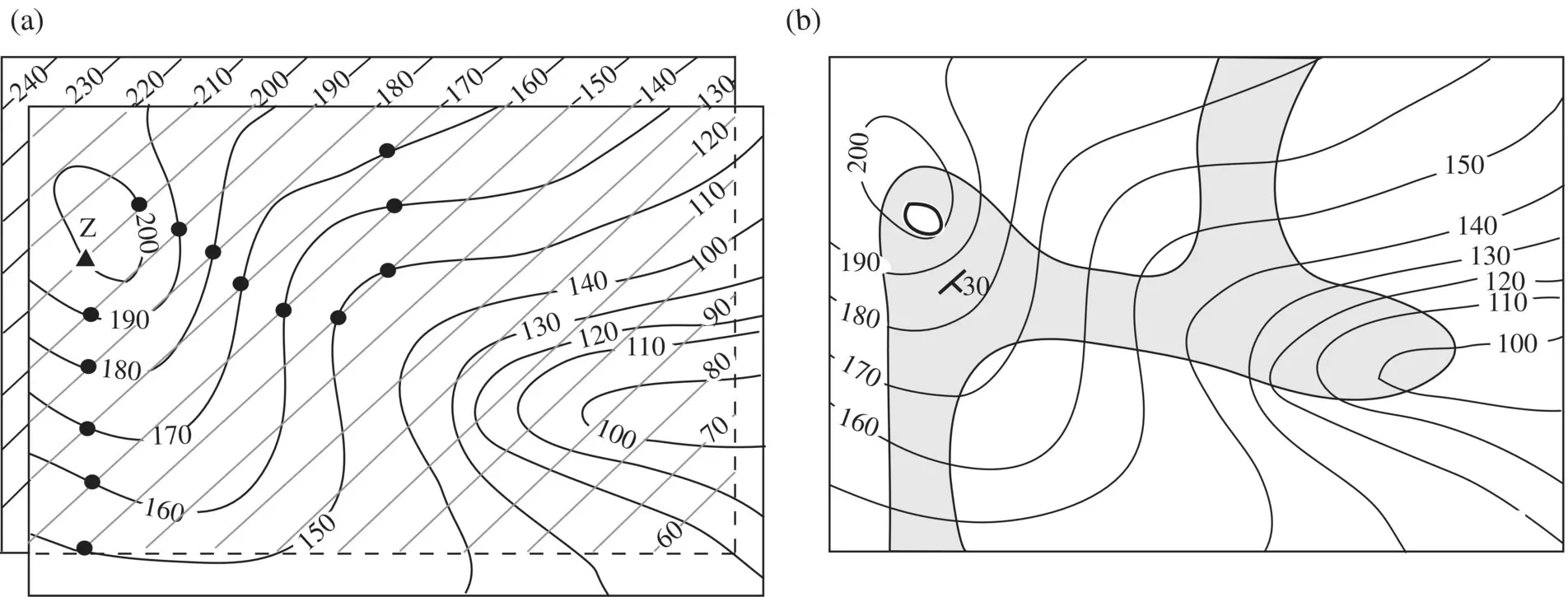
Figure 2.14 (a) Structure‐contour map from Figure 2.13shifted such that the 200‐ft structure contour lies on point Z. Point Z is a point where the bottom of a layer is exposed. The top of this same layer is exposed at points A, B, and C from Figure 2.11a. (b) Outcrop pattern of this layer, which dips 30° to the southeast.
1 Position the structure‐contour map beneath the topographic map such that the bottom surface outcrop point (or points) lies (lie) at the proper elevation on the structure‐contour map. With the structure contours parallel to their former position, proceed as before. In Figure 2.14a, point Z, at an elevation of 200 ft, is an outcrop of the bottom of the bed. The structure‐contour map has been moved so that the 200‐ft structure contour passes through point Z, and the predicted outcrop points have been located as before.
2 Once the upper and lower contacts are drawn on the topographic map, the outcrop pattern of the bed can be shaded or colored ( Figure 2.14b).
 Figure P2.4is a topographic map of an area that contains an industrial landfill that is leaking leachate into the groundwater system. Points a, b, and c are wells that were drilled at the same time and penetrate the water table. The depth of the water table in each well is 12 ft for a, 10 ft for b, and 27 ft for c. Scale bar is 10 ft. See Video 2 at https://youtu.be/GBpY_Vi0zMw.
1 Assuming that the water table is planar, construct structure contours for the water table.
2 Draw the cross section X to X’, showing the topography and the water table.
3 Shade the area where the properties would be impacted by the pollutant plume.
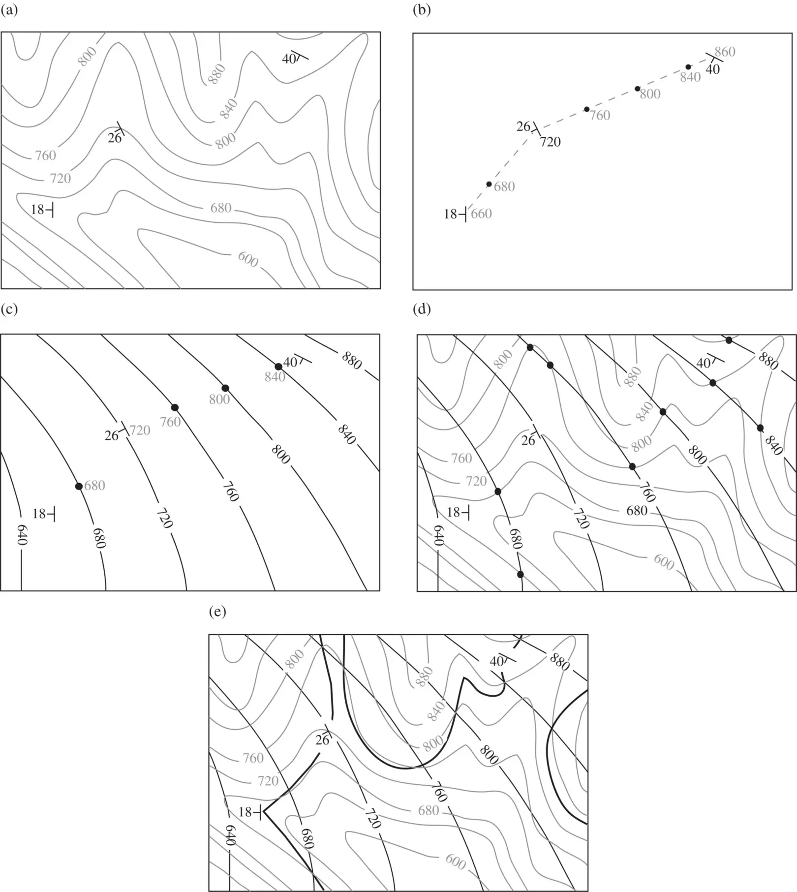
The technique of gently bent layers for locating the intersection of a geologic surface with the surface of the earth may be roughly used if the surface has a simple change in dip and a structure‐contour map can be constructed. In Figure 2.15a, three attitudes of a marker bed are mapped and all are different. Assuming a constant slope and a gradual change in dip between outcrop points, a structure‐contour map may be constructed as follows:
1 Arithmetically interpolate between the known elevation points to locate the necessary elevation points on the surface ( Figure 2.15b).
2 Draw smooth parallel structure contours parallel to the strikes at the outcrop points ( Figure 2.15c).
3 Superimpose the structure contour map and the topographic map and mark the points where contours of equal elevation intersect ( Figure 2.15d).
4 Connect these intersection points to produce the outcrop map ( Figure 2.15e).
Figure P2.5is a topographic map. Points A, B, and C are outcrop points of the upper surface of a planar coal seam. Point Z is an outcrop point of the base of the coal seam.
1 Determine the attitude of the coal seam.
2 Draw the outcrop pattern of the coal seam.
3 Determine the thickness of the coal seam. Attach any drawings and computations you use.

Figure 2.15 Determination of outcrop pattern of a gently bent surface using structure contours. (a) Attitude of a gently folded marker bed at three points on a topographic map. (b) Interpolation of elevations between points of known elevation. (c) Structure‐contour map of a gently folded bed. (d) Structure‐contour map superimposed on topographic base. (e) Inferred outcrop pattern of marker bed.
Determining Exact Attitudes from Outcrop Patterns
Because the strike of a plane is a horizontal line, any line drawn between points of equal elevation on a plane defines the plane's strike. Figure 2.16a is a geologic map with two rock units, Formation M and Formation X. The contact between these units crosses several topographic contours. To find the strike of the contact, a straight line is drawn from the intersection of the contact with the 1920‐ft contour on the west side of the map to the intersection of the contact with the 1920‐ft contour on the east side of the map ( Figure 2.16b). The strike of this contact is determined to be 079° (N79E), as measured directly on the geologic map using a protractor.
Читать дальше


 Figure P2.4is a topographic map of an area that contains an industrial landfill that is leaking leachate into the groundwater system. Points a, b, and c are wells that were drilled at the same time and penetrate the water table. The depth of the water table in each well is 12 ft for a, 10 ft for b, and 27 ft for c. Scale bar is 10 ft. See Video 2 at https://youtu.be/GBpY_Vi0zMw.


