Engineering Solutions for CO2 Conversion
Здесь есть возможность читать онлайн «Engineering Solutions for CO2 Conversion» — ознакомительный отрывок электронной книги совершенно бесплатно, а после прочтения отрывка купить полную версию. В некоторых случаях можно слушать аудио, скачать через торрент в формате fb2 и присутствует краткое содержание. Жанр: unrecognised, на английском языке. Описание произведения, (предисловие) а так же отзывы посетителей доступны на портале библиотеки ЛибКат.

- Название:Engineering Solutions for CO2 Conversion
- Автор:
- Жанр:
- Год:неизвестен
- ISBN:нет данных
- Рейтинг книги:3 / 5. Голосов: 1
-
Избранное:Добавить в избранное
- Отзывы:
-
Ваша оценка:
Engineering Solutions for CO2 Conversion: краткое содержание, описание и аннотация
Предлагаем к чтению аннотацию, описание, краткое содержание или предисловие (зависит от того, что написал сам автор книги «Engineering Solutions for CO2 Conversion»). Если вы не нашли необходимую информацию о книге — напишите в комментариях, мы постараемся отыскать её.
Engineering Solutions for CO2 Conversion — читать онлайн ознакомительный отрывок
Ниже представлен текст книги, разбитый по страницам. Система сохранения места последней прочитанной страницы, позволяет с удобством читать онлайн бесплатно книгу «Engineering Solutions for CO2 Conversion», без необходимости каждый раз заново искать на чём Вы остановились. Поставьте закладку, и сможете в любой момент перейти на страницу, на которой закончили чтение.
Интервал:
Закладка:
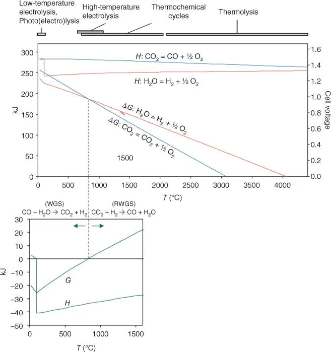
Figure 3.6Enthalpy and free energy of CO 2and H 2O reduction reactions and water gas shift reaction (WGSR). The present figure has been taken from the Grave's review.
Source: Graves et al. [102].
If co‐electrolysis is conducted, the WGSR has to be taken into account, and the system becomes more complicated. At temperatures above the zero free energy, reverse water gas shift reaction (RWGSR) is favored. As results, co‐electrolysis is usually run by systems that work at high temperature (solid oxide electrolyzers).
3.5.1.1 Water Electrolysis
The electrolyzer can be depicted as an electrolyte placed between two electrodes (anode and cathode) connected electrically by an external circuit. In most electrolyzers, the electrolyte is an ion‐selective membrane and works due to the electrochemical gradient generated in the cell. The principle of the transport is ascribed to the compensation of charges in the system by charge‐carrying species. For polymeric membranes, a functional group is introduced in the polymer structure to induce the ionic conductivity, whereas in solid oxide materials, defects are generated into the crystalline structure to enhance the O 2−or H +transport.
Electrolyzers can be classified according to the materials used for the cell construction, operation temperature, and charge carriers. Considering the charge carrier in the electrolyte, the main electrolyzers can be divided into three groups:
Hydroxide anion (OH−).○ Alkaline electrolysis cell (AEC): Water is decomposed into hydrogen and HO− at the cathode. The hydroxide anion migrates to the anode, through the electrolyte, generating oxygen. The electrolyte solution consists of a mixture of water and NaOH or KOH. Among the electrolysis technologies, the alkaline electrolysis of water is the most mature technology and a long‐time commercial technology.○ Polymer alkaline electrolyzer cell (PAEC): The main difference with the previous electrolyzer lies in the electrolyte; instead of using a liquid electrolyte, a polymeric membrane with OH− ions conductivity is employed.
Proton (H+).○ Proton exchange membrane electrolysis cell (PEMEC): The two half cells are separated by a polymeric membrane. Protons are generated in the anode and then they pass by the membrane, generating hydrogen in the cathode. Because of the low temperature, expensive noble metals are used generally on both electrodes, the most common is platinum, and high external voltages are required to overcome the reaction kinetics.○ Proton conductor solid oxide electrolyzer cell (PC‐SOEC): All components in the cell are solids and high operation temperatures (600–1000 °C) are required for the cell operation to favor the electronic and/or ionic conductivity of materials. As in the PEM electrolyzers, the protons are generated in the cathode and are recombined in the anode to produce hydrogen. Membrane is based on a proton conductor material.
Oxygen ions (O2−).○ Solid oxide electrolyzer cell (SOEC): Oxygen ions generated in the cathode are conducted toward the anode through an oxygen ion conductor membrane. All components of the cell are solids and work at high operation temperature.
The main components and most common materials for the cell construction of each type of electrolyzer are summarized in Table 3.2.
Despite the fact that SOEC technology is a more mature technology, proton conductor electrolysis cell (PCEC) technology presents the advantage of producing directly dry pressurized H 2and subsequently the need of less separation steps. In addition, operation temperatures are lower (500–700 °C), allowing the reduction of the material cost.
Recently, a study about the first fully operational PCEC has been published [106]. A tubular supported electrolyte made of BaZr 0.7Ce 0.2Y 0.1O 2.95and Ba 1−xGd 0.8La 0.2+xCo 2O 6−δas a steam anode was employed and a hydrogen production above 15 N ml min −1was obtained. In addition, Faradaic efficiencies close to 100% at high steam pressures were observed.
Table 3.2Summary of main characteristics of electrolyzers [103–105].
Source: Adapted from Millet et al. [103], Laguna‐Bercero [104], and Sakai et al. [105].
| AEC | PAEC | PEMEC | PC‐SOEC | SOEC | ||
|---|---|---|---|---|---|---|
| Anode | Reaction | 4OH −→ 2H 2O + O 2+ 4e − | 4OH −→ 2H 2O + O 2+ 4e − | 2H 2O → 4H ++ O 2+ 4e − | 2H 2O → 4H ++ O 2+ 4e − | |
| O 2−→ 1/ 2O 2+ 2e − | Materials | Ni–Co–Fe, Ni 2CoO 4, La–Sr–CoO 3, Co 3O 4 | Ni‐based | Ir, Ru oxide | BCZY, SCZY | La xSr 1−xMnO 3+ Y‐stabilized ZrO 2(YSZ) |
| Electrolyte | Charge carrier | OH − | OH − | H + | H + | O 2− |
| Materials | Liquid: 25–30 wt% (KOH) aq | Solid: polymeric | Solid: polymeric | Solid: BCZY, BZY, BCY, proton conductors | Solid: Y 2O 3–ZrO 2, Sc 2O 3–ZrO 2, MgO–ZrO 2, CaO–ZrO 2 | |
| Cathode | Reaction | 2H 2O + 4e −→ 4OH −+ 2H 2 | 2H 2O + 4e −→ 4OH −+ 2H 2 | 4H ++ 4e −→ 2H 2 | 4H ++ 4e −→ 2H 2 | H 2O + 2e −→ O 2−+ H 2 |
| Materials | Nickel foam/Ni alloys; Ni–Mo/ZrO 2–TiO 2 | Ni, Ni–Fe, NiFe 2O 4 | Pt/C, MoS 2 | Ni cermets | Ni‐YSZ | |
| Operation temperature | 20–80 °C | 20–200 °C | 20–200 °C | 600–1000 °C | 600–1000 °C |
Table 3.3Summary of main features of CO electrolyzers or co‐electrolyzers.
| MCEC | SOEC | PC‐SOEC | ||
|---|---|---|---|---|
| Anode | Reaction | CO 3 2−→ 1/2O 2+ CO 2+ 2e − | O 2−→ 1/2O 2+ 2e − | 2H 2O → 4H ++ O 2+ 4e − |
| Materials | Nickel based | La xSr 1−xMnO 3+ Y‐stabilized ZrO 2(YSZ) | BCZY, SCZY | |
| Electrolyte | Charge carrier | CO 3 2− | O 2− | H + |
| Materials | Molten carbonates | Solid: Y 2O 3–ZrO 2, Sc 2O 3–ZrO 2, MgO–ZrO 2, CaO–ZrO 2 | Solid: BCZY, BZY, BCY, proton conductors | |
| Cathode | Reaction | H 2O + CO 2+ 2e −→ H 2+ CO 3 2−2CO 2+ 2e −→ CO + CO 3 2− | H 2O + 2e −→O 2−+ H 2CO 2+ 2e −rarr; CO + O 2− | 4H ++ 4e −→ 2H 2CO 2+ 2H ++ 2e −→ CO + H 2O |
| Materials | Nickel‐based | Ni‐YSZ | Ni cermets | |
| Operation temperature | 600–800 °C | 600–1000 °C | 600–1000 °C |
3.5.1.2 CO 2Co‐electrolysis
Electrochemical CO 2reduction has gained importance in the field of energy storage and conversion, and the catalysts and electrolytes influence not only the catalytic activity and selectivity of the reaction, but also on the CO 2reduction mechanism to different species [107].
High temperature is desired for the CO 2electrolysis ( Figure 3.6), and among the electrolysis systems, molten carbonate electrolyzer cells (MCECs), SOEC, and PC‐SOEC are favored for the CO 2direct valorization by electrolysis ( Table 3.3).
Because CO 2, H 2O, and H 2are involved in the reactions, the system is further complicated when the co‐electrolysis takes places, a scheme with all the species and reactions involved is represented in Figure 3.7.
Among the Co‐electrolyzers at high temperatures, solid oxide cells (PC‐SOEC and SOEC) present two main advantages. First, all components in the cells are solids and the risk of liquid leakage is avoided. Secondly, high temperature facilitates the electrolysis because the kinetics and thermodynamics are favored.
Читать дальшеИнтервал:
Закладка:
Похожие книги на «Engineering Solutions for CO2 Conversion»
Представляем Вашему вниманию похожие книги на «Engineering Solutions for CO2 Conversion» списком для выбора. Мы отобрали схожую по названию и смыслу литературу в надежде предоставить читателям больше вариантов отыскать новые, интересные, ещё непрочитанные произведения.


Обсуждение, отзывы о книге «Engineering Solutions for CO2 Conversion» и просто собственные мнения читателей. Оставьте ваши комментарии, напишите, что Вы думаете о произведении, его смысле или главных героях. Укажите что конкретно понравилось, а что нет, и почему Вы так считаете.