3D Printing for Energy Applications
Здесь есть возможность читать онлайн «3D Printing for Energy Applications» — ознакомительный отрывок электронной книги совершенно бесплатно, а после прочтения отрывка купить полную версию. В некоторых случаях можно слушать аудио, скачать через торрент в формате fb2 и присутствует краткое содержание. Жанр: unrecognised, на английском языке. Описание произведения, (предисловие) а так же отзывы посетителей доступны на портале библиотеки ЛибКат.
- Название:3D Printing for Energy Applications
- Автор:
- Жанр:
- Год:неизвестен
- ISBN:нет данных
- Рейтинг книги:5 / 5. Голосов: 1
-
Избранное:Добавить в избранное
- Отзывы:
-
Ваша оценка:
3D Printing for Energy Applications: краткое содержание, описание и аннотация
Предлагаем к чтению аннотацию, описание, краткое содержание или предисловие (зависит от того, что написал сам автор книги «3D Printing for Energy Applications»). Если вы не нашли необходимую информацию о книге — напишите в комментариях, мы постараемся отыскать её.
Readers will also benefit from the inclusion of
A thorough introduction to 3D printing of functional materials, including metals, ceramics, and composites An exploration of 3D printing challenges for production of complex objects, including computational design, multimaterials, tailoring AM components, and volumetric AM Practical discussions of 3D printing of energy devices, including batteries, supercaps, solar panels, fuel cells, turbomachinery, thermoelectrics, and CCUS Perfect for materials scientists,
will also earn a place in the libraries of graduate students in engineering, chemistry, and material sciences seeking a one-stop reference for current and future perspectives on 3D printing of high value-added complex devices.
3D Printing for Energy Applications — читать онлайн ознакомительный отрывок
Ниже представлен текст книги, разбитый по страницам. Система сохранения места последней прочитанной страницы, позволяет с удобством читать онлайн бесплатно книгу «3D Printing for Energy Applications», без необходимости каждый раз заново искать на чём Вы остановились. Поставьте закладку, и сможете в любой момент перейти на страницу, на которой закончили чтение.
Интервал:
Закладка:
Functionally graded metal lattice structures with tailored mechanical response are most commonly used in biomedical applications like implants. The human bone is a functionally graded anisotropic structure, and hence any biocompatible implants need to have similar mechanical performance. A large surface area also helps toward osseointegration and thus leads to fewer implant rejections. A large body of research thus focuses on scaffolds of biocompatible materials like CoCrMo, Titanium alloys, and, more recently, biodegradable alloys of Mg, Zn, and Fe [30]. Hazlehurst, Wang, and Stanford [31] investigated L‐PBF of CoCrMo FGMs to imitate bone for a hip implant that is half as light, and twice as flexible compared to a solid metal structure. Ataee, Li, Fraser, Song, and Wen [32] researched high porosity (82–85%) Ti64 scaffolds with varying unit cell dimensions by EB‐PBF and found that the ratio of elastic modulus anisotropy in orthogonal directions was comparable to those of a human trabecular bone. Yan, Hao, Hussein, and Young [33] and Yu, Sun, and Bai [34] focused on increasing the surface area by using Triply Periodic Minimal Surfaces (TPMS) in their lattice designs. Zhang, Fang, Leeflang, Zadpoor, and Zhou [35] took an alternate approach through a stepwise topological design based on diamond unit cells to mimic the structure of the femoral diaphysis through L‐PBF of Ti‐6Al‐4V.
1.2.2 Material Gradients in PBF
The application of multi‐materials in a component expands the already large design space provided by additive manufacturing processes. Directed energy deposition processes (DED) are typically associated with multi‐material additive manufacturing in metals due to their intrinsic system‐related flexibility of changing to different feedstocks during operation, as further discussed in Section 1.3. However, PBF‐based additive manufacturing processes exhibit specific advantages over DED. A prominent example is the possibility to generate more intricate geometries and achieve smaller feature sizes. At the same time, most commercially available PBF systems are limited to a single powder feedstock restricting the deployment of different materials during the build process. This section deals with Type‐II, III material gradients in PBF [36].
The most common kind of multi‐material PBF components are Type‐II involving the use of an existing prefabricated structure of material A and adding a second material B. While the process itself doesn't change, the multi‐material components often reduce the manufacturing time thus combining the best of conventional and additive manufacturing. Another Type‐II multi‐material methodology involves premixed powder compositions that offer significant improvements in desired properties. The review paper by Bandyopadhyay and Heer [20] showcases several examples of Type‐II PBF multi‐material. More recently, Chen et al. [37] investigated L‐PBF of steel–bronze multi‐material components and found brittle cracks at the interface. Hinojos et al. [38] used EB‐PBF to make IN718/SS316 and SS316/IN718 components and found that the high temperatures in EB‐PBF make it less susceptible to solidification cracking. AlMangour, Grzesiak, and Yang [39], Han et al. ([40]), Kun, Beibei, Wenheng, and Cailin ([41]), and Xia et al. [42] worked with premixed titanium composite powders to improve the wear resistance and hardness of L‐PBF Ti parts. Recent works successfully demonstrated microstructural control during PBF to make Type‐III components. Niendorf et al. [43] used process control to modify the microstructure of SS316 in L‐PBF and Koptyug et al. [44] used a similar mechanism in EB‐PBF of SS316. Biondani, Bissacco, Mohanty, Tang, and Hansen [45] showcased a hybrid process chain to make Type‐II multi‐material L‐PBF components with a mirror‐like finish for molding applications.
Anstaett, Seidel, and Reinhart [46] from Fraunhofer, IGCV showcased a multi‐material FGAM part of Copper–Chrome–Zirconia and Tool Steel 1.2790. New systems were used for handling the selective layout of powder within the individual recoated layer for powder‐bed systems [47]. Demir and Previtali [48] introduced a prototype L‐PBF system with two powder feeders in combination with piezoelectric transducers for in‐situ gradual mixing of Fe and Al‐12Si powder. Wei, Li, Zhang, and Chueh [49] demonstrated, for the first time, full spatial control in all directions in L‐PBF using a custom‐made system with multiple powder feeders and a point‐by‐point micro‐vacuum selective material‐removing system. Figure 1.3shows the schematic of an Aurora Labs system with custom‐built software for multi‐material processing at DTU [36]. The powder feeder systems are accurate within a 1% error by weight of powder dispensed per layer. This allows precise control of the mixing percentage within each layer. An example is presented with a graded Type‐III steel sample with a hard phase (SS440C) and a soft phase (SS316L) alternating sinusoidally. Preliminary microstructure and microhardness tests reveal that the component is functionally graded as designed. One of the primary concerns of multi‐material PBF is the issue of material waste, due to difficulties in recycling the powder. Aerosint solves this issue through selective powder deposition. At DTU, the issue is addressed by means of tracking software, which automatically adjusts the ratio of the powder materials based on the history of the mixed powder and desired final composition per layer. Bodner et al. [50] used a unique PBF system with integrated liquid dispersed metal powder dispensation. The setup was used to additively manufacture a multilayered structure based on alternating Inconel 625 alloy (IN625) and 316L stainless steel (316L) layers on a 316L base plate. New methodologies for applying multi‐material powder in PBF are necessary for the wider adoption of FGAM components for critical functional applications.
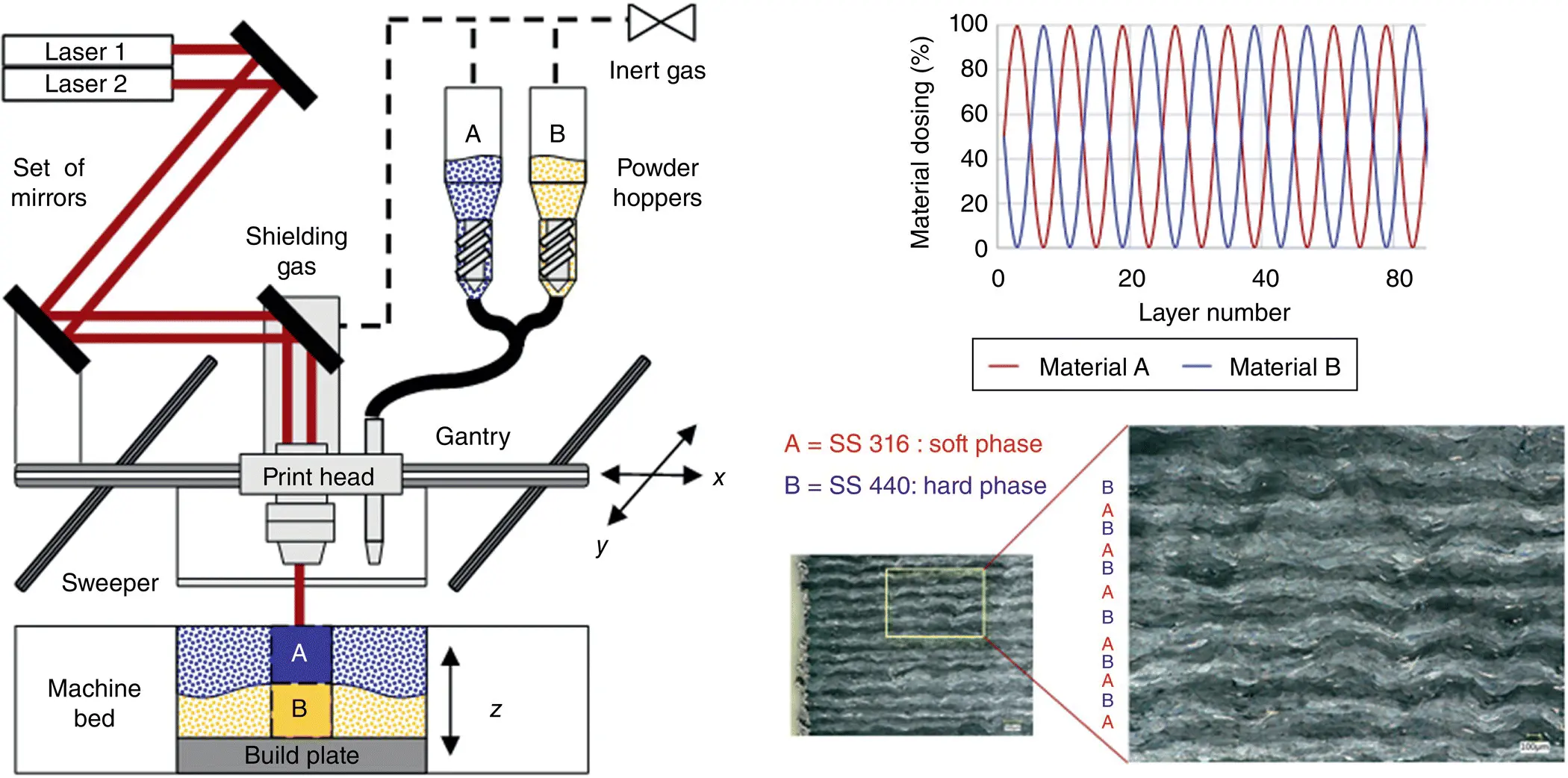
Figure 1.3 Working schematic of the L‐PBF equipment, and functionally graded steel composite components built at The Technical University of Denmark (DTU).
1.3 Direct Material Deposition
1.3.1 Powder and Wire Feedstock for Near‐Net‐Shape AM
Direct Material Deposition (DMD) can be divided into two classes of AM processes based on the feedstock being powder or wire. The class of powder feedstock systems is called Directed Energy Deposition (DED), and with wire, the systems are classified underwire arc additive manufacturing (WAAM) [51]. In both cases, the deposition head consists of a power source (Laser/Wire arc) and a material deposition module to continuously add new material into the process. Often the deposition head is mounted on a five‐axis robot, and typically, there is an option to mix multiple materials in‐situ. The material flexibility in DMD processes makes them the most suitable for manufacturing functionally graded AM components. Theoretically, any additive process that allows adjustment of feedstock material mid‐build is viable. However, directed energy deposition (DMD) processes lend themselves best to functional grading due to the comparatively small feedstock losses as opposed to multi‐material PBF, since powder blends cannot be easily separated and recycled for reuse. Figure 1.4shows a schematic of the DED process, wherein the deposition head is mounted on a five‐axis robot. Up to six materials can be used simultaneously in the setup. Laser deposited materials experience a complex thermal history marked by rapid solidification, high cooling rates, steep thermal gradients, and cyclic reheating and cooling from multiple laser passes. This can lead to the formation of nonequilibrium microstructures and significant variations in microstructure from layer to layer, as well as within individual layers. Hence, an online process‐control is achieved with the help of an in‐axis thermal camera that ensures similar thermal gradients in each new layer.
Читать дальшеИнтервал:
Закладка:
Похожие книги на «3D Printing for Energy Applications»
Представляем Вашему вниманию похожие книги на «3D Printing for Energy Applications» списком для выбора. Мы отобрали схожую по названию и смыслу литературу в надежде предоставить читателям больше вариантов отыскать новые, интересные, ещё непрочитанные произведения.


Обсуждение, отзывы о книге «3D Printing for Energy Applications» и просто собственные мнения читателей. Оставьте ваши комментарии, напишите, что Вы думаете о произведении, его смысле или главных героях. Укажите что конкретно понравилось, а что нет, и почему Вы так считаете.