Rajib Taid - Mobile Communications Systems Development
Здесь есть возможность читать онлайн «Rajib Taid - Mobile Communications Systems Development» — ознакомительный отрывок электронной книги совершенно бесплатно, а после прочтения отрывка купить полную версию. В некоторых случаях можно слушать аудио, скачать через торрент в формате fb2 и присутствует краткое содержание. Жанр: unrecognised, на английском языке. Описание произведения, (предисловие) а так же отзывы посетителей доступны на портале библиотеки ЛибКат.
- Название:Mobile Communications Systems Development
- Автор:
- Жанр:
- Год:неизвестен
- ISBN:нет данных
- Рейтинг книги:5 / 5. Голосов: 1
-
Избранное:Добавить в избранное
- Отзывы:
-
Ваша оценка:
Mobile Communications Systems Development: краткое содержание, описание и аннотация
Предлагаем к чтению аннотацию, описание, краткое содержание или предисловие (зависит от того, что написал сам автор книги «Mobile Communications Systems Development»). Если вы не нашли необходимую информацию о книге — напишите в комментариях, мы постараемся отыскать её.
Mobile Communications Systems Development: A Practical Approach for System Understanding, Implementation and Deployment In-depth chapters cover the entire protocol stack from the Physical (PHY) to the Application layer, discuss theoretical and practical considerations, and describe software implementation based on the 3GPP standardized technical specifications. The book includes figures, tables, and sample computer code to help readers thoroughly comprehend the functions and underlying concepts of a mobile communications network. Each chapter includes an introduction to the topic and a chapter summary. A full list of references, and a set of exercises are also provided at the end of the book to test comprehension and strengthen understanding of the material. Written by a respected professional with more than 20 years’ experience in the field, this highly practical guide:
Provides detailed introductory information on GSM, GPRS, UMTS, and LTE mobile communications systems and networks Describes the various aspects and areas of the LTE system air interface and its protocol layers Covers troubleshooting and resolution of mobile communications systems and networks issues Discusses the software and hardware platforms used for the development of mobile communications systems network elements Includes 5G use cases, enablers, and architectures that cover the 5G NR (New Radio) and 5G Core Network
is perfect for graduate and postdoctoral students studying mobile communications and telecom design, electronic engineering undergraduate students in their final year, research and development engineers, and network operation and maintenance personnel.
Mobile Communications Systems Development — читать онлайн ознакомительный отрывок
Ниже представлен текст книги, разбитый по страницам. Система сохранения места последней прочитанной страницы, позволяет с удобством читать онлайн бесплатно книгу «Mobile Communications Systems Development», без необходимости каждый раз заново искать на чём Вы остановились. Поставьте закладку, и сможете в любой момент перейти на страницу, на которой закончили чтение.
Интервал:
Закладка:
Broadcasting of network system information to mobile devices,
Radio resource allocation for CS (GSM) and PS services.
CS (GSM) and PS call setup, supervise, and its release, Figure 3.7 LTE network end‐to‐end control plane protocol layers.Source: © 2015. 3GPP ™ TSs and TRs are the property of ARIB, ATIS, CCSA, ETSI, TSDSI, TTA and TTC who jointly own the copyright in them. © 2015, 3GPP.
MM functions and procedures such as the GSM location update, handover, GPRS routing area, LTE/EPS tracking area update procedure, and 5G registration area update procedure, and
GPRS, LTE/EPS SM functions and procedures such as Packet Data Protocol Context Creation and Bearer Allocation.
However, the air interface control plane protocol stack and layers also perform different functions and procedures that are specific to a particular communications system, i.e. GSM, GPRS, UMTS, LTE, and 5G systems. For example, the following functions are performed by the UMTS, LTE, and 5G air interface control plane protocol stacks only:
Header compression,
Establishments of radio bearers,
Configurations of lower layers, e.g. PDCP and RLC, by another higher‐layer RRC,
Ensuring the ciphering, integrity, and security protection of the information exchanged between UE and RAN and CN, and
Provision for a transparent mode (TM) of user data transfer.
Using the control plane protocol layers functions and procedures, the RAN or CN controls and commands the behavior of an MS/UE. For more information on the control plane protocol functions and procedures by the individual protocol layer of a logical interface, refer to the 3GPP TSs mentioned in the References section of this book.
3.2.2 User Plane Protocols
User plane protocol layers perform the functions required to transmit and receive the user/application traffic between the source and destination network element and vice versa. As an example, Figure 3.8shows the end‐to‐end LTE system, TS 23.401 [39], user plane protocol layers structure starting from the UE, eNodeB, and S‐GW to P‐GW.
At the UE end, the user plane protocols consist of the application layer, IP layer, PDCP, RLC, MAC, and physical layer. Note that the application and IP layers terminate at the P‐GW. The IP layer contains the source and destination IP addresses using which the P‐GW receives/route the user application data packets toward the external packet data network. The air interface layers (RLC, MAC, and PDCP) terminate at the eNodeB end.
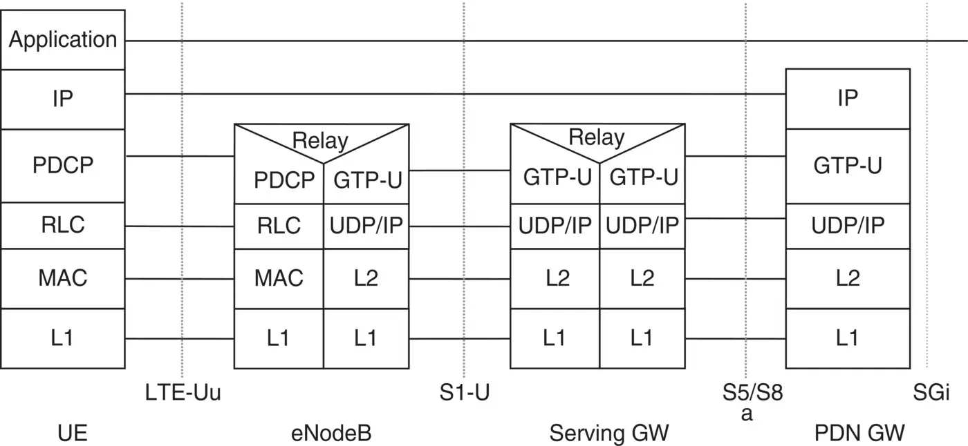
Figure 3.8 LTE UE – P‐GW user plane protocol layers.
Source: © 2015. 3GPP ™ TSs and TRs are the property of ARIB, ATIS, CCSA, ETSI, TSDSI, TTA and TTC who jointly own the copyright in them. © 2015, 3GPP.
Example 3.5File Transfer Protocol (FTP) Protocol
Consider the File Transfer Protocol (FTP) that is used to upload and download files between two different hosts. FTP uses port number 20 to transfer user data, whereas it uses port number 21 to exchange control commands between the two communicating hosts. Here, one will find that the FTP also uses the so‐called user and control plane concept to facilitate the exchange of control and data transfer between two hosts.
Example 3.6GPRS Tunneling Protocol
The GTP has the control as well as the user plane protocols. The tunnel management is taken care of by the so‐called GPRS tunneling Control Protocol, whereas the user IP data packets/payload is transported using the GTP‐User Plane T‐PDU (tunneled PDU) as shown later in Figure 8.1. GTP is used in a couple of interfaces in GPRS, UMTS, LTE/EPS, and 5G CN. For more information on the GTP control and user plane protocol, refer to TS 29.060 [67], 29.274 [70], and TS 29.281 [72].
At the LTE/EPC end, the user plane of the eNodeB, S‐GW, and P‐GW consists of the GTP‐user plane [12] to tunnel user data on top of the UDP/IP transport network. Figure 3.8also shows the respective user plane logical interfaces, i.e. S1‐U and S5/S8, for carrying user data between two network elements of an LTE/EPS network.
From Figures 3.7and 3.8, it is observed that in the LTE system, the radio interface protocol layers – PDCP, RLC, and MAC, are available in both the control plane and the user plane protocol stack. In the user plane protocol stack, the application and IP layers terminate at the CN, P‐GW, which transfers user data packets to the external network. Examples 3.5and 3.6describe two typical protocols consisting of control plane and user plane protocol.
3.3 Grouping of UMTS, LTE, and 5G Air Interface Protocol Layers
In the previous section, we have mentioned about the classifications of protocol layers into the control plane or signaling and user plane . In the case of UMTS, LTE, and 5G systems, their air interface control plane or signaling protocol layers are further grouped into what is called the Access Stratum ( AS) ) and NAS layer . The word “ Stratum ” means a grouping of protocols that is related to one service aspect of the various services provided by one or several network elements. The LTE, 5G, and UMTS system air interface protocol layer groupings are illustrated in Figure 3.9.
3.3.1 Access Stratum (AS): UMTS UE – UTRAN; LTE UE – E‐UTRAN;5G UE ‐ NG‐RAN
The AS contains radio air interface signaling protocol layers between UE and UTRAN; UE and E‐UTRAN; and UE‐5G NG‐RAN only. The AS signaling protocol messages terminate at the UMTS UTRAN, LTE E‐UTRAN, and 5G NG‐RAN end. As the name implies, the AS contains all the protocols using which a UMTS or LTE or 5G UE communicates with the UMTS UTRAN or LTE E‐UTRAN or 5G NG‐RAN only to transmit/receive signaling messages over their respective radio air interfaces.
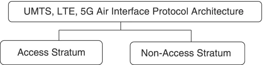
Figure 3.9 UMTS, LTE, and 5G air interface protocol layer groups.
Table 3.6 UMTS and LTE access stratum control plane protocol layers.
| Protocol Category | System | |
|---|---|---|
| Air Interface Access Stratum Protocol Layers | UMTS/UTRAN AS Layers | LTE/E‐UTRAN AS Layers |
| Physical, MAC, RLC, RRC | Physical, MAC, RLC, PDCP, RRC |
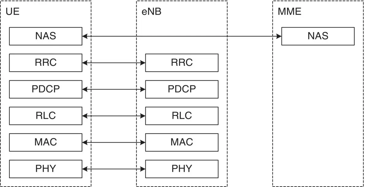
Figure 3.10 LTE E‐UTRAN: access stratum and non‐access stratum protocol stack.
Source: © 2015. 3GPP ™ TSs and TRs are the property of ARIB, ATIS, CCSA, ETSI, TSDSI, TTA and TTC who jointly own the copyright in them. © 2015, 3GPP.
The UMTS and LTE AS and its control or signaling plane protocol layers, over the air interface Uu, are shown in Table 3.6. The AS and NAS protocol structures for the LTE system air interface are shown in Figure 3.10, which is reproduced from TS 36.300 [92].
The typical flow of AS signaling messages, i.e. RRC layer, between a UE and the LTE/E‐UTRAN is described in Example 3.7below.
Example 3.7LTE AS Layer: Radio Resource Connection Establishment Procedure
Интервал:
Закладка:
Похожие книги на «Mobile Communications Systems Development»
Представляем Вашему вниманию похожие книги на «Mobile Communications Systems Development» списком для выбора. Мы отобрали схожую по названию и смыслу литературу в надежде предоставить читателям больше вариантов отыскать новые, интересные, ещё непрочитанные произведения.


Обсуждение, отзывы о книге «Mobile Communications Systems Development» и просто собственные мнения читателей. Оставьте ваши комментарии, напишите, что Вы думаете о произведении, его смысле или главных героях. Укажите что конкретно понравилось, а что нет, и почему Вы так считаете.