Rajib Taid - Mobile Communications Systems Development
Здесь есть возможность читать онлайн «Rajib Taid - Mobile Communications Systems Development» — ознакомительный отрывок электронной книги совершенно бесплатно, а после прочтения отрывка купить полную версию. В некоторых случаях можно слушать аудио, скачать через торрент в формате fb2 и присутствует краткое содержание. Жанр: unrecognised, на английском языке. Описание произведения, (предисловие) а так же отзывы посетителей доступны на портале библиотеки ЛибКат.
- Название:Mobile Communications Systems Development
- Автор:
- Жанр:
- Год:неизвестен
- ISBN:нет данных
- Рейтинг книги:5 / 5. Голосов: 1
-
Избранное:Добавить в избранное
- Отзывы:
-
Ваша оценка:
Mobile Communications Systems Development: краткое содержание, описание и аннотация
Предлагаем к чтению аннотацию, описание, краткое содержание или предисловие (зависит от того, что написал сам автор книги «Mobile Communications Systems Development»). Если вы не нашли необходимую информацию о книге — напишите в комментариях, мы постараемся отыскать её.
Mobile Communications Systems Development: A Practical Approach for System Understanding, Implementation and Deployment In-depth chapters cover the entire protocol stack from the Physical (PHY) to the Application layer, discuss theoretical and practical considerations, and describe software implementation based on the 3GPP standardized technical specifications. The book includes figures, tables, and sample computer code to help readers thoroughly comprehend the functions and underlying concepts of a mobile communications network. Each chapter includes an introduction to the topic and a chapter summary. A full list of references, and a set of exercises are also provided at the end of the book to test comprehension and strengthen understanding of the material. Written by a respected professional with more than 20 years’ experience in the field, this highly practical guide:
Provides detailed introductory information on GSM, GPRS, UMTS, and LTE mobile communications systems and networks Describes the various aspects and areas of the LTE system air interface and its protocol layers Covers troubleshooting and resolution of mobile communications systems and networks issues Discusses the software and hardware platforms used for the development of mobile communications systems network elements Includes 5G use cases, enablers, and architectures that cover the 5G NR (New Radio) and 5G Core Network
is perfect for graduate and postdoctoral students studying mobile communications and telecom design, electronic engineering undergraduate students in their final year, research and development engineers, and network operation and maintenance personnel.
Mobile Communications Systems Development — читать онлайн ознакомительный отрывок
Ниже представлен текст книги, разбитый по страницам. Система сохранения места последней прочитанной страницы, позволяет с удобством читать онлайн бесплатно книгу «Mobile Communications Systems Development», без необходимости каждый раз заново искать на чём Вы остановились. Поставьте закладку, и сможете в любой момент перейти на страницу, на которой закончили чтение.
Интервал:
Закладка:
3.1 Protocol Interface and Its Stack
Network elements of mobile communications networks are designed and developed based on a set of standard protocols and specifications as defined by the 3GPP. A protocol interface is a communication path that is established between two network elements. Each network element and its protocol layers communicate with the peer network element and its protocol layers through a particular interface. The related protocol layers or the protocol stack, supported by a network element, are organized into a protocol interface . Over a particular protocol interface between two network elements, they exchange various signaling messages corresponding to a particular function and procedure such as the following ones:
Call Control Management, i.e. a call establishment, maintenance, and its releasing;
Mobility Management and Session Management (SM);
Radio Resource Management, Handover, and Power Control Management; and
Interworking, Interoperations, Roaming Management, and so on.
A protocol interface also carries user data or traffic between two network elements. A protocol interface between two network elements could be physical as well as logical as described below. A logical interface may be a point to point, i.e. direct, or may span through several network elements. A logical interface works on top of a physical interface.
3.1.1 Physical Interface
The physical interface defines the electrical characteristic of the physical transmission media being used for the actual transmission and reception of information between a sender and receiver. Consider the physical Cat5 cable or its other variants used in a Local Area Network to transmit and receive upper/lower layers information. Application data received from the upper layers are converted into Ethernet frames. The network interface card (NIC)/Ethernet chipset generates the required electrical signals to transmit the frames through the Cat5/6 physical cable/layer. The NIC/Ethernet driver also knows when to read and write binary data from the physical interface and layer.
Similarly, in the case of a mobile communications system also, various physical transmission interfaces/media are used across the different systems, i.e. GSM to 5G, to transmit either signaling or user traffic between two network elements. Being the GRPS CN, LTE/Evolved Packet Core (EPC) and 5G as an IP network‐based system, the IP transport network is used to transmit and receive information among their network elements. Example s 3.1and 3.2below illustrate the typical physical interfaces found in mobile communications systems, from the GSM to the 5G system.
3.1.2 Logical Interface
In computer network programming, an interface is a logical point, such as a socket where two different applications/systems exchange information and communicate with each other in terms of a protocol data unit (PDU). Similarly, in the case of mobile communications networks also, two different network elements communicate, either signaling or user data, with each other using a set of predefined messages or PDUs. These collective PDUs or messages define the particular logical interface between two network elements.
A logical interface works on top of a particular physical interface. Using a logical interface, network entities exchange both the user data and signaling information in the form of a message or a PDU. For example, consider the GSM A‐bis interface between the BTS and BSC and the A‐interface between the BSC and the MSC. Both of these logical interfaces work on top of the physical E1 interface to transport signaling and user traffic in a GSM network. Typical signaling messages exchanged over the A‐bis interface are radio resources request and allocation to an MS and its release and so on.
Example 3.1GSM E1 Physical Interface
One of the most commonly used physical interfaces is the E1 , which is defined under the standard G.703 of ITU‐T [12]. An E1 physical interface is not only used in the mobile communications system but also used in other systems to carry voice, data, and so on. For example, E1 physical interface is used between the GSM Base Station Controller (BSC) and Base Transceiver Station (BTS); GSM BSC, and Mobile Switching Center (MSC), or between the MSC and Serving GPRS Support Node (SGSN) for the Gs interface. An E1 physical interface has two pair/four wire cables for both Receive (RX) and Transmit (TX) purposes. The total bandwidth supported by the E1 interface is the 2 Mbps that is divided into 32 timeslots of 64 kbps each. Each 64 kbps timeslot is again divided into four sub‐timeslots. A sub‐timeslot can be allocated to a GSM voice call or General Packet Radio Service (GPRS) data communication purpose. Figure 3.1illustrates the configuration and usages of an E1 physical interface to carry signaling as well as user traffic. Using an E1 interface, several transceivers (TRXs), along with their signaling channels, of a BTS can be configured.
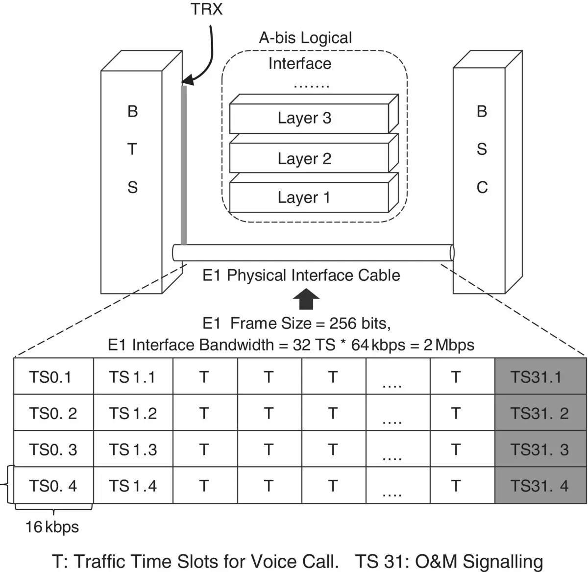
Figure 3.1 Illustration: physical E1 interface configuration for GSM A‐bis interface.
Example 3.2Mobile Communications Networks and Their Physical Air Interface
An MS/UE communicates with the RAN of the GSM/GPRS, UMTS, LTE, and 5G systems through their respective air interface between them. The air interface is the physical interface where the actual physical link/interface/transmission media used over the air interface is the radio wave . A radio wave carries the modulated information between the UE/MS and RAN and vice versa. The air interface between the MS/UE and GSM RAN, UMTS UTRAN, LTE Evolved‐UMTS Terrestrial Radio Access Network (E‐UTRAN), and 5G RAN is illustrated, in general, in Figure 3.2below.
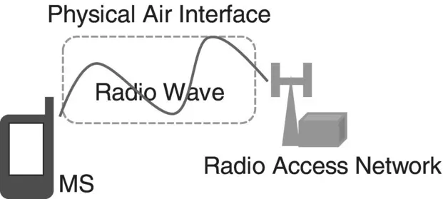
Figure 3.2 Illustration: physical air interface for GSM, UMTS, LTE, and 5G NR systems.
A logical interface may consist of a protocol stack that may contain several protocol layers in it. Protocol layers are grouped into a particular logical interface which is known by a particular logical interface name for ease of its identification. Examples 3.3and 3.4below illustrate the typical logical interfaces found in the LTE/EPS and the 5G system.
The S1 logical interface between the LTE eNodeB and EPC contains two types of protocol stacks that are used to carry signaling and user data; see Figure 3.3a and b:
User data transmission protocol, also called user plane, S1‐U.
Signaling or control plane protocol, called control plane, S1‐Application Protocol (AP).
Similarly, the NG logical interface between the 5G NG‐RAN/gNB and UPF contains two types of protocol stacks that are used to carry signaling and user data; see Figure 3.3a and b:
User data transmission protocol, also called user plane, NG‐U.
Signaling or control plane protocol, called control plane, NG‐AP.
The S1‐U or NG‐U user plane protocol stack is used to transfer user traffic or data between the respective RAN (LTE eNodeB or 5G gNB) and its CN element (LTE/EPS MME or 5G UPF). The control plane protocol stack, S1‐AP(LTE/EPS) or NG‐AP (5G), is used to transfer signaling messages between the respective RAN (LTE eNodeB or 5G gNB) and its CN element (LTE/EPS MME or 5G AMF). Figure 3.3a shows side‐by‐side the S1‐U and NG‐U user plane protocol stacks, and Figure 3.3b shows the S1‐AP and NG‐AP signaling or control plane protocol stacks.
Читать дальшеИнтервал:
Закладка:
Похожие книги на «Mobile Communications Systems Development»
Представляем Вашему вниманию похожие книги на «Mobile Communications Systems Development» списком для выбора. Мы отобрали схожую по названию и смыслу литературу в надежде предоставить читателям больше вариантов отыскать новые, интересные, ещё непрочитанные произведения.


Обсуждение, отзывы о книге «Mobile Communications Systems Development» и просто собственные мнения читателей. Оставьте ваши комментарии, напишите, что Вы думаете о произведении, его смысле или главных героях. Укажите что конкретно понравилось, а что нет, и почему Вы так считаете.