Rajib Taid - Mobile Communications Systems Development
Здесь есть возможность читать онлайн «Rajib Taid - Mobile Communications Systems Development» — ознакомительный отрывок электронной книги совершенно бесплатно, а после прочтения отрывка купить полную версию. В некоторых случаях можно слушать аудио, скачать через торрент в формате fb2 и присутствует краткое содержание. Жанр: unrecognised, на английском языке. Описание произведения, (предисловие) а так же отзывы посетителей доступны на портале библиотеки ЛибКат.
- Название:Mobile Communications Systems Development
- Автор:
- Жанр:
- Год:неизвестен
- ISBN:нет данных
- Рейтинг книги:5 / 5. Голосов: 1
-
Избранное:Добавить в избранное
- Отзывы:
-
Ваша оценка:
Mobile Communications Systems Development: краткое содержание, описание и аннотация
Предлагаем к чтению аннотацию, описание, краткое содержание или предисловие (зависит от того, что написал сам автор книги «Mobile Communications Systems Development»). Если вы не нашли необходимую информацию о книге — напишите в комментариях, мы постараемся отыскать её.
Mobile Communications Systems Development: A Practical Approach for System Understanding, Implementation and Deployment In-depth chapters cover the entire protocol stack from the Physical (PHY) to the Application layer, discuss theoretical and practical considerations, and describe software implementation based on the 3GPP standardized technical specifications. The book includes figures, tables, and sample computer code to help readers thoroughly comprehend the functions and underlying concepts of a mobile communications network. Each chapter includes an introduction to the topic and a chapter summary. A full list of references, and a set of exercises are also provided at the end of the book to test comprehension and strengthen understanding of the material. Written by a respected professional with more than 20 years’ experience in the field, this highly practical guide:
Provides detailed introductory information on GSM, GPRS, UMTS, and LTE mobile communications systems and networks Describes the various aspects and areas of the LTE system air interface and its protocol layers Covers troubleshooting and resolution of mobile communications systems and networks issues Discusses the software and hardware platforms used for the development of mobile communications systems network elements Includes 5G use cases, enablers, and architectures that cover the 5G NR (New Radio) and 5G Core Network
is perfect for graduate and postdoctoral students studying mobile communications and telecom design, electronic engineering undergraduate students in their final year, research and development engineers, and network operation and maintenance personnel.
Mobile Communications Systems Development — читать онлайн ознакомительный отрывок
Ниже представлен текст книги, разбитый по страницам. Система сохранения места последней прочитанной страницы, позволяет с удобством читать онлайн бесплатно книгу «Mobile Communications Systems Development», без необходимости каждый раз заново искать на чём Вы остановились. Поставьте закладку, и сможете в любой момент перейти на страницу, на которой закончили чтение.
Интервал:
Закладка:
Example 3.3LTE/EPC S1 Logical Interface and 5G NG Logical Interface
Consider the S1 logical interface between the eNodeB and the EPC (consisting of Serving Gateway (S‐GW), Mobility Management Entity (MME), and packet data network gateway (P‐GW)) in the case of the LTE/EPC network. Similarly, consider the NG logical interface between the Next Generation Radio Access Network (NG‐RAN)/gNB and the User Plane Function ( UPF ) in the case of the 5G network. Refer to Figure 3.3a and b.
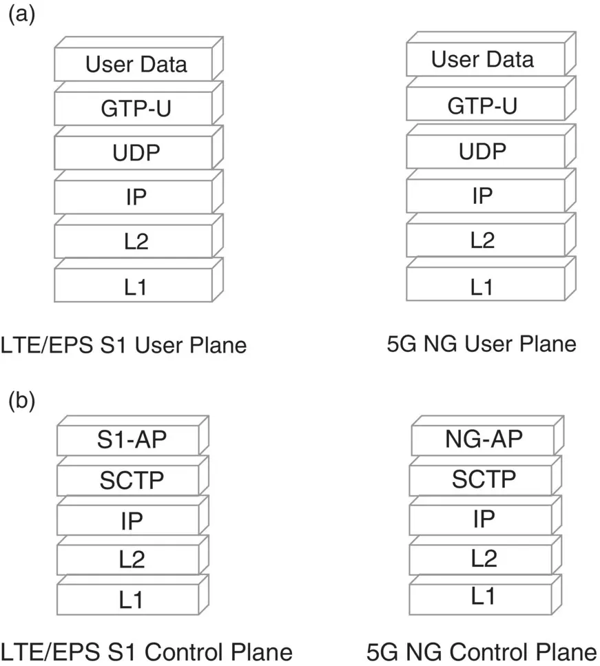
Figure 3.3 (a) LTE S1 and 5G NG logical interface: user plane. (b) LTE S1 and 5G NG logical interface: control plane.
Figure 3.3shows that the S1‐U and NG‐U or the S1‐AP and the NG‐AP have the same protocol stack over the IP transport network. Protocol layer classifications under user plane and control plane protocols are described later in Section 3.2.
Example 3.4LTE Logical Interfaces with the Same Protocol Stack
In the LTE/EPS mobile communications network, several logical interfaces may have the same protocol stack and its transport network. For example, consider the IP transport‐based logical interfaces: S3 (MME‐SGSN), S4 (S‐GW‐SGSN), S5 and S8 (S‐GW – P‐GW), S10 (MME‐MME), and S11 (MME‐S‐GW) that are used among the several network elements of an LTE/EPS network. These logical interfaces have the same protocol stack on top of the IP transport network, i.e. UDP/IP, which is used to tunnel IP payload from one network element to its peer. Refer to the illustration shown in Figure 3.4. IP payload is tunneled through a protocol called GPRS Tunneling Protocol ( GTP ) in an encapsulated manner. GTP PDUs between two network elements are transported on top of the underlying IP transport network.
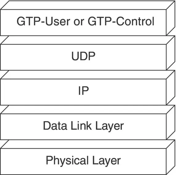
Figure 3.4 LTE/EPS logical interfaces: S3, S4, S5, S8, S10, and S11 protocol stack.
Note that in the case of the LTE/EPS system, the GTP control plane Version 2 (GTP‐C v2) [70] is used in all the logical interfaces mentioned above to carry signaling information between their respective network elements. But in the case of the GPRS/UMTS system, GTP control plane Version 1 (GTP‐C v1) TS 29.060 [67] is used. Similarly, the GTP‐user plane, TS 29.281 [72], protocol is used to carry user traffic/data between their respective network elements.
To achieve successful interoperability between two network elements from two different vendors, it is important to understand the concerned protocol specification, encode/decode, and implement correctly each message/PDUs defined in a particular logical interface and its protocol specification. Different logical interfaces may use different physical transmission media to transport the messages of a logical interface. All the IP transport‐based mobile communications protocols will use the Stream Control Transmission Protocol ( SCTP ) RFC 4960 [17] or UDP protocol suite and UTP CAT cable as physical media.
3.1.3 Logical Interfaces’ Names and Their Protocol Stack
In a computer network, the TCP/IP protocol suite has a collection of protocols that are classified and grouped into four layers, namely the application layer, transport layer, network layer, and the physical layer. By referring to the TCP/IP protocol suite, one can easily recall the various layers and protocols available under it.
Similarly, a logical interface in mobile communications networks also consists of a protocol stack and its layers. To identify and refer such protocol stack and its layers, each logical interface is given an identification name that begins with a capitalized English alphabet letter. For example, in the previous section, the LTE/EPS logical interface S1 or 5G NG logical interface was discussed. Similar examples of other logical interfaces are A‐interface between the BSC and MSC, Gs interface between the MSC and SGSN, A‐bis interface between the BTS and BSC, Iu interface between RNC and MSC, and so on.
There are large numbers of logical interfaces connecting different network elements of GSM, GPRS, UMTS, LTE/EPS, and 5G networks. To provide a brief overview to the reader, the following Tables 3.1to 3.4lists the names of some of the logical interfaces, second row, along with their network elements, first row, used in the GSM, GPRS, UMTS, and LTE/EPS networks.
The reader may refer to the corresponding technical specification(s) which are available on the 3GPP site [1] for further information on the logical interfaces mentioned in Tables 3.1to 3.4.
Table 3.5summarizes the various logical as well as the physical interfaces being used between the respective RAN and the CN in the GSM, GPRS, UMTS, LTE, and 5G systems.
Table 3.1 GSM and GPRS system network elements and logical interfaces.
| Air Interface (MS‐BSC) | BTS‐BSC | BSC‐MSC | BSC‐SGSN | SGSN‐GGSN |
|---|---|---|---|---|
| Um | A‐bis | A | Gb | Gn |
Table 3.2UMTS system network elements and logical interfaces.
| Air Interface (UE‐NodeB) | Node‐RNC | RNC‐MSC | RNC‐SGSN | SGSN‐GGSN | GGSN‐WWW |
|---|---|---|---|---|---|
| Uu | Iub | Iu‐CS | Iu‐PS | Gn | Gi |
Table 3.3LTE/EPS network elements and logical interfaces.
| Air Interface (UE‐eNodeB) | eNodeB‐MME | eNodeB‐S‐GW | S‐GW ‐ P‐GW | P‐GW ‐ WWW |
|---|---|---|---|---|
| Uu | S1‐AP | S1‐U | S5 | SGi |
Table 3.4 Interworking features and their logical interfaces.
| 3GPP Feature: CSFB (MME‐MSC) | Feature: SRVCC (MME‐MSC, MSC‐SGSN) |
|---|---|
| SGs | Sv |
Table 3.5 Logical and physical interface between RAN and CN elements.
| System | Interface Between Network Element | Logical Interface Name | Physical Interface Name | |
|---|---|---|---|---|
| GSM | BSC | MSC | A‐interface | E1 |
| GPRS | BSC | SGSN | Gb‐interface | E1, IP Layer 1 |
| UMTS | RNC | MSC | Iu‐CS | PDH, SDH, IP Layer 1 |
| SGSN | Iu‐PS | PDH, SDH, IP Layer 1 | ||
| LTE | E‐UTRAN | MME | S1(S1‐AP) | IP Layer 1 |
| S‐GW | S1(S1‐U) | IP Layer 1 | ||
| 5G | NG‐RAN | AMF | NG (NG‐AP) | IP Layer 1 |
For more information on all the 3GPP defined logical interfaces, their protocol stack/layers, and network elements of mobile communications networks, refer to the 3GPP TS 23.003 [30]. The next section illustrates the logical interfaces and their physical transmission network used in a typical GSM and GPRS network.
3.1.4 Examples of Logical Interface and Its Protocol Layers
Section 3.1.2described the different logical interfaces used among the LTE/EPC or 5G network elements where user data or signaling information is transported over the same underlying IP transport network. However, in a GPRS and GSM network, different transport networks may be used apart from the IP network as illustrated below:
Читать дальшеИнтервал:
Закладка:
Похожие книги на «Mobile Communications Systems Development»
Представляем Вашему вниманию похожие книги на «Mobile Communications Systems Development» списком для выбора. Мы отобрали схожую по названию и смыслу литературу в надежде предоставить читателям больше вариантов отыскать новые, интересные, ещё непрочитанные произведения.


Обсуждение, отзывы о книге «Mobile Communications Systems Development» и просто собственные мнения читателей. Оставьте ваши комментарии, напишите, что Вы думаете о произведении, его смысле или главных героях. Укажите что конкретно понравилось, а что нет, и почему Вы так считаете.