Rajib Taid - Mobile Communications Systems Development
Здесь есть возможность читать онлайн «Rajib Taid - Mobile Communications Systems Development» — ознакомительный отрывок электронной книги совершенно бесплатно, а после прочтения отрывка купить полную версию. В некоторых случаях можно слушать аудио, скачать через торрент в формате fb2 и присутствует краткое содержание. Жанр: unrecognised, на английском языке. Описание произведения, (предисловие) а так же отзывы посетителей доступны на портале библиотеки ЛибКат.
- Название:Mobile Communications Systems Development
- Автор:
- Жанр:
- Год:неизвестен
- ISBN:нет данных
- Рейтинг книги:5 / 5. Голосов: 1
-
Избранное:Добавить в избранное
- Отзывы:
-
Ваша оценка:
Mobile Communications Systems Development: краткое содержание, описание и аннотация
Предлагаем к чтению аннотацию, описание, краткое содержание или предисловие (зависит от того, что написал сам автор книги «Mobile Communications Systems Development»). Если вы не нашли необходимую информацию о книге — напишите в комментариях, мы постараемся отыскать её.
Mobile Communications Systems Development: A Practical Approach for System Understanding, Implementation and Deployment In-depth chapters cover the entire protocol stack from the Physical (PHY) to the Application layer, discuss theoretical and practical considerations, and describe software implementation based on the 3GPP standardized technical specifications. The book includes figures, tables, and sample computer code to help readers thoroughly comprehend the functions and underlying concepts of a mobile communications network. Each chapter includes an introduction to the topic and a chapter summary. A full list of references, and a set of exercises are also provided at the end of the book to test comprehension and strengthen understanding of the material. Written by a respected professional with more than 20 years’ experience in the field, this highly practical guide:
Provides detailed introductory information on GSM, GPRS, UMTS, and LTE mobile communications systems and networks Describes the various aspects and areas of the LTE system air interface and its protocol layers Covers troubleshooting and resolution of mobile communications systems and networks issues Discusses the software and hardware platforms used for the development of mobile communications systems network elements Includes 5G use cases, enablers, and architectures that cover the 5G NR (New Radio) and 5G Core Network
is perfect for graduate and postdoctoral students studying mobile communications and telecom design, electronic engineering undergraduate students in their final year, research and development engineers, and network operation and maintenance personnel.
Mobile Communications Systems Development — читать онлайн ознакомительный отрывок
Ниже представлен текст книги, разбитый по страницам. Система сохранения места последней прочитанной страницы, позволяет с удобством читать онлайн бесплатно книгу «Mobile Communications Systems Development», без необходимости каждый раз заново искать на чём Вы остановились. Поставьте закладку, и сможете в любой момент перейти на страницу, на которой закончили чтение.
Интервал:
Закладка:
GPRS Gb‐Interface Protocol Stack and Layers
In the case of the GPRS system, the Gb‐interface between the BSC and the SGSN is used for transferring the signaling and user data exchanged between the MS and the SGSN. The GPRS Gb interface consists of the following applications protocol layers:
BSSSGP – Base Station Subsystem GPRS Protocol
NS – Network Service
The Network Service (NS) layer is further divided into the following components:
Network Service Control (NSC) Protocol
Sub‐Network Service (SNS) Protocol
The Gb interface stack with the above protocol layers follows the protocol structure shown in Figure 3.5. Below the NS layer, there are two transmission network protocols, having its physical layer and media that can be used to exchange upper‐layer information between the Base Station Subsystem (BSS) and the SGSN. Those transport networks are:
Frame Relay (FR) Protocol Transmission Network and
IP Transmission Network.
Based on the transmission network protocol, Frame Relay, or IP, shown in Figure 3.5, the concerned physical layer shall be used accordingly. Note that the Gb‐interface cannot use both the Frame Relay and the IP transmission network simultaneously but shall use only one transmission network, either Frame Relay or IP, at a time. The particular transmission network to be used is configured by the operator and maintenance personnel, and it is taken care of by the SNS Protocol at the NS layer level.
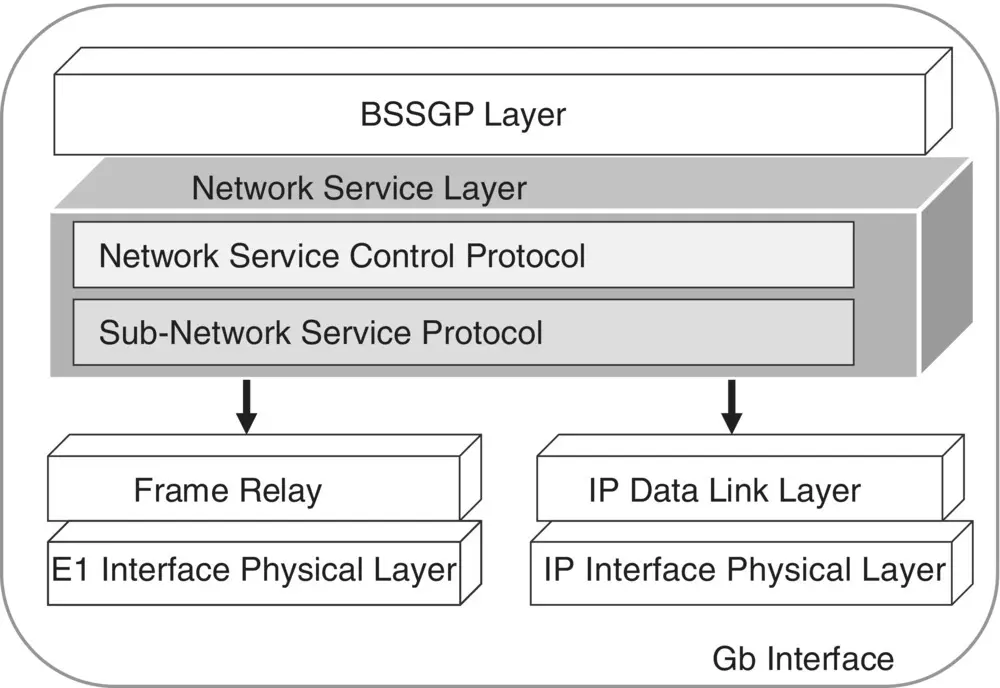
Figure 3.5 GPRS: Gb‐interface protocol stack with IP and frame relay transport network.
The NS Control Protocol deals with transferring of the information of the upper layer in the form of NS Data Units (NS SDU), whereas the SNS Protocol deals with the management of the underlying transmission network protocol (Frame Relay or IP) to be used at a time to transfer upper‐layer information. For further details on the GPRS NS layer, refer to TS 48.016 [135].
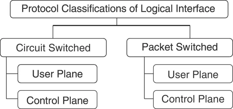
Figure 3.6 Protocol layers classifications in GSM, GPRS, UMTS, LTE, and 5G systems.
3.2 Classifications of Protocol Layers
In a mobile communications network, the circuit‐switched (GSM, UMTS) or packet‐switched (UMTS, LTE, 5G) domain protocol layers of a protocol stack that belongs to a particular logical interface are classified into the following categories ( Figure 3.6):
Control Plane or Signaling Plane
User Plane or Data Plane
3.2.1 Control Plane or Signaling Protocols
What is a Signaling Message?
One important aspect of a mobile communications network is the “signal” that is exchanged between the network elements. Mobile communications signaling is nothing but an exchange of information between the concerned network elements prior to providing communications services to a subscriber or another network element. Signaling messages among the network elements are exchanged to reserve resources as part of the call setup and release the resources as part of the call release procedure. In addition to this, signaling messages are exchanged to carry out various functions and procedures among the network elements of GSM/GPRS, UMTS, LTE/EPS, and 5G networks. By exchange of signaling information among the network elements, necessary logical objects, or contexts, a database of various information is created at the UE/MS, RAN, and CN end. Information such as the capabilities of a particular MS/UE, radio access, and CN capabilities and their features, information about a subscriber, and so on are also exchanged only through signaling, which is updated at the UE/MS, RAN, and CN end.
In a traditional Public Switched Telephone Network (PSTN) fixed network also, signaling functions are performed for call establishing, maintaining, and supervision and call release. Note that control/signaling plane messages last for a fraction of a second only to setup and release a call or to perform other procedures among the network elements. Before a user can start communications services, a signaling procedure or phase must be completed successfully between a UE/MS and the RAN, between the RAN and CN, and between the UE and CN. For example, an MS/UE must be registered with the CN through a successful GSM location area or GPRS routing area or LTE/EPS tracking area update or 5G Registration Request procedure. Prior to performing such signaling procedures, a UE/MS must request and be allocated the necessary radio resources by the GSM BSC, UMTS RNC, or LTE eNodeB or 5G NG‐RAN through signaling only. All such signaling procedures in a particular mobile communications network are performed by its control plane protocol stack and its layers only.
If there is a signaling congestion situation in a network, an MS/UE would not get the requested resources from the network. Thus, a mobile user would not be able to make a circuit‐switched (CS) or a packet‐switched (PS) call. This would further require the troubleshooting of the issue or a proper radio network planning by the operator.
LTE/EPS Network Control Plane Protocols: UE – eNodeB – MME
Figure 3.7shows the end‐to‐end control plane protocol layers of an LTE network, which is reproduced from TS 23.401 [39].
The LTE air interface control plane protocol layers between the UE and E‐UTRAN are Radio Resource Control (RRC), Packet Data Convergence Protocol (PDCP), Radio Link Control (RLC), and Media Access Control (MAC) layer. Between the UE and the MME, the control plane protocol layer is known as the Non‐Access Stratum (NAS) layer, consisting of the EPS Mobility Management (EMM) and ESM protocols. On the CN side, the control plane protocol is S1‐AP/MME AP between eNodeB and MME. The S1‐AP control messages are transported over the SCTP [17]. The EPS mobility and SM layer performs similar functions and procedures as described above for the GPRS control plane protocols. The RRC protocol layer is responsible for providing a reliable link between the UE and the MME in the case of the LTE/EPS network ( Figure 3.7). Beyond the LTE/EPC MME, it uses the GTP control plane [11] protocol to perform tunnel management procedures with the S‐GW.
The Relay as shown in Figure 3.7is not a protocol layer but an application module that is responsible for the reconstruction or reassembly of information transmitted by the lower layer, i.e. RLC or RRC. A common module also available in GPRS, UMTS, LTE RAN, and 5G NG‐RAN is the Relay module. In the GPRS/UMTS system, the Relay module forwards the reformatted data to the GPRS BSSGP or UMTS Radio Access Network Application Part (RANAP) layer in terms of PDUs for onward transmission to the SGSN over the Gb or Iu‐PS interface. Similarly, in LTE/EPS, the Relay module forwards data to the MME over the S1 interface. In 5GS, the Relay module forwards data to the AMF and UPF. The relay module is required to follow the underlying protocol layer details to reassemble their data for onward transmission to the CN.
Functions of Control PlaneProtocol: Air interface
The control plane protocol stack performs different functions according to its logical interface. From the air interface point of view, some of the common functions and procedures, in general, performed by the control plane protocol stack and layers in the GSM, GPRS, UMTS, LTE/EPS, and 5G system are as follows. These functions are similar though their protocol layer specification and implementation aspects are different:
Читать дальшеИнтервал:
Закладка:
Похожие книги на «Mobile Communications Systems Development»
Представляем Вашему вниманию похожие книги на «Mobile Communications Systems Development» списком для выбора. Мы отобрали схожую по названию и смыслу литературу в надежде предоставить читателям больше вариантов отыскать новые, интересные, ещё непрочитанные произведения.


Обсуждение, отзывы о книге «Mobile Communications Systems Development» и просто собственные мнения читателей. Оставьте ваши комментарии, напишите, что Вы думаете о произведении, его смысле или главных героях. Укажите что конкретно понравилось, а что нет, и почему Вы так считаете.